Table of Contents
Advertisement
Quick Links
A C - P R O - I I
®
I - A C - P R O - I I
A C T R I P UNI T
I N STRU C TI O N m A N U A L
S
T A T E O F T HE A R T T E C HNO L O G Y F O R L O W
V O L T A G E C I R C UI T B R E A K E R R E T R O F I T T I NG
C h a g r i n F a l l s , O H 4 4 0 2 3
P h o n e : 8 8 8 . 2 8 9 . 2 8 6 4
www. u t i l i t y r e l a y . c o m
Advertisement
Table of Contents

Related Manuals for Utility Relay Company AC-PRO-II

Summary of Contents for Utility Relay Company AC-PRO-II
- Page 1 A C - P R O - I I ® I - A C - P R O - I I A C T R I P UNI T I N STRU C TI O N m A N U A L T A T E O F T HE A R T T E C HNO L O G Y F O R L O W V O L T A G E C I R C UI T B R E A K E R R E T R O F I T T I NG C h a g r i n F a l l s , O H 4 4 0 2 3...
-
Page 3: Table Of Contents
20.1 Internal Error ..........44 10.0 Sluggish Breaker Detection ......... 20 20.2 Actuator Open Circuit ........44 ® 11.0 Commissioning the AC-PRO-II ......21 20.3 Alarm Screens ..........44 11.1 Powering-Up the Trip Unit for Commissioning . 21 20.4 Un-Calibrated ..........44 11.1.1 Internal Battery........ - Page 4 Page Figure 4.1 AC-PRO-II Front View - Horizontal Configuration ......................5 Figure 4.2: AC-PRO-II Front View - Vertical Configuration with Breaker Harness at bottom ............6 Figure 4.3: AC-PRO-II Side View (without VDM) ..........................6 Figure 4.4: AC-PRO-II Angled Views – with and without VDM ...................... 7 Figure 4.5: AC-PRO-II connectors and cables ..........................
-
Page 5: Introduction And Product Overview
600 Volt class, AC circuit The AC-PRO-II can be provided with an optional Voltage breakers on 50 Hertz or 60 Hertz systems. The AC-PRO-II Divider Module (VDM) attached to the back of the trip unit. -
Page 6: Ul/Ulc Classification & Ce Mark
2.0 UL/ULC Classification & CE Mark 3.2 Battery Power AC-PRO-II® is currently UL and ULC classified for use on A 3-Volt, 850 mAh, CR2, long life Lithium battery is used in the following low voltage AC power circuit breakers: the trip unit. -
Page 7: Pictures And Configurations
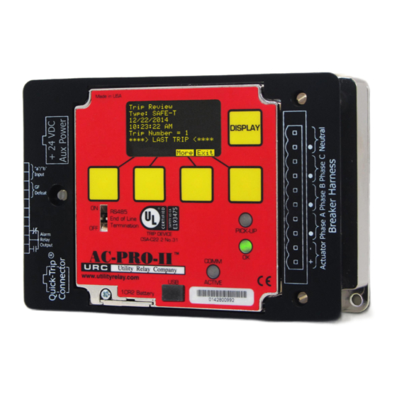
Instruction Manual www.utilityrelay.com ® 4.0 AC-PRO-II Pictures and Configurations Figure 4.1 AC-PRO-II Front View - Horizontal Configuration Local Display (rotatable) Red PICK-UP LED The Local Display is normally mounted to the trip This LED will illuminate if the current exceeds the unit. -
Page 8: Figure 4.2: Ac-Pro-Ii Front View - Vertical Configuration With Breaker Harness At Bottom
® AC-PRO-II Instruction Manual www.utilityrelay.com Figure 4.2: AC-PRO-II Front View - Vertical Configuration with Breaker Harness at bottom AC-PRO-II Trip Unit Trip Unit Wire Cover Local Display Figure 4.3: AC-PRO-II Side View (without VDM) Page 6... -
Page 9: Figure 4.4: Ac-Pro-Ii Angled Views – With And Without Vdm
Module (VDM) Connector Covers Shown with VDM and wire cover Shown without VDM and without wire cover Figure 4.4: AC-PRO-II Angled Views – with and without VDM Breaker Harness Optional Neutral CT Cable Optional Communications Cable and connector and connector assembly and connector assembly Figure 4.5: AC-PRO-II connectors and cables... -
Page 10: External Connections
® AC-PRO-II Instruction Manual www.utilityrelay.com 5.0 External Connections Figure 5.1: AC-PRO-II External Connections - Vertical Bottom Configuration (Breaker Harness at bottom, shown with wiring cover off) Auxiliary Terminal Block Configurable alarm relay output Ground Fault Defeat input Breaker position contact input... -
Page 11: Figure 5.2: Voltage Divider Module (Vdm) External Connections
® AC-PRO-II Instruction Manual www.utilityrelay.com Voltage Divider Module (VDM) Mounted on Back of AC-PRO-II Voltage Divider Module (VDM) External Connections Figure 5.2: Voltage Divider Module (VDM) External Connections Page 9... -
Page 12: Figure 5.3: Ac-Pro-Ii Typical Wiring Diagram
Neutral CT is optional. Only for 4-wire Neutral systems with Ground Fault Protection and/or CT Configuration shown Neutral Overload Normal Power Flow allows for Residual protection. Ground Fault protection and Neutral Overload Protection. Figure 5.3: AC-PRO-II Typical Wiring Diagram Page 10... -
Page 13: Breaker Wiring Harness
The ground fault function on a 3-wire system does not require a neutral CT. Additionally, this All AC-PRO-II trip units are equipped with the capability of connection method allows Neutral Overload Protection to be connecting to an AC-PRO-II QUICK-TRIP Switch, which implemented. -
Page 14: Ground Fault Defeat Input
If no other power source is available, the battery is used to reset the alarm relay. (applies to manual resets only) If the AC-PRO-II is installed on a breaker where the face of the trip unit is not concealed by a cubicle door, the USB port on the face of the trip unit itself can be safely accessed. -
Page 15: Usb Extension Cable Installation
5. Connect the right-angle USB connector to the c. 485 (RS485 Communication Settings): This AC-PRO-II. Route the cable so it does not interfere with sub-menu is for changing RS485 the opening or closing of the cubical door or with the communications settings only. -
Page 16: Table 6-A: Common Smart Button Actions
® AC-PRO-II Instruction Manual www.utilityrelay.com Smart Action Button Label Next Proceed to next screen or next setting Return the previous screen or previous Back setting Exit Return to the Main Screen Increase setting value or toggle to next setting value. -
Page 17: Figure 6.2: Typical Ac-Pro-Ii Menu Navigation Map - Simple View
UNDERVOLTAGE ALARM SETTING / SCREEN WILL APPEAR IF VDM MODULE IS CONNECTED. NOTE: THIS IS A TYPICAL MAP. SCREENS & SEQUENCES VARY DEPENDING ON ORDER CODES AND SETTINGS. Figure 6.2: Typical AC-PRO-II Menu Navigation Map - Simple View Page 15... -
Page 18: Power Menu
For details regarding Settings, refer to Section 11.0. Trip History Menu The AC-PRO-II stores data from the last eight (8) trips. The trip history menu displays this information. The trip unit stores trip counts, types, time stamps, and currents. If a VDM is connected, voltages will also be stored in the trip history. -
Page 19: Battery Test And Status
Display since they can Firm. Rev. x.x.xx.xxx be separated. Util Time Exit Next Utility Relay Co. Time And Date Manually Clear All AC-PRO-II LOCAL Alarms and Reset xx:xx:xx PM DISPLAY Information xx/xx/xxxx S/N xxxxxxxxxx Alarm Relay? Firm. Rev. x.x.xx.xxx Next Reset Back... -
Page 20: Quick-Trip System (Optional)
QUICK-TRIP settings reducing the Arc Flash “Push-to-Verify” button is available. Pressing this button will Hazard to personnel. “wake up” the trip unit using the AC-PRO-II battery, and the QUICK-TRIP ON LED will illuminate, providing positive When the maintenance work is finished, the QUICK-TRIP... -
Page 21: Ac-Pro-Ii Quick-Trip Switch Mounting
Attach the QUICK-TRIP Switch to the front of the cubicle door using the two (2) supplied 10-32 screws Figure 7.4: AC-PRO-II QUICK-TRIP Switch and lock washers. Connect the QUICK-TRIP Switch to the AC-PRO-II trip ® Remote QUICK-TRIP Switch unit by plugging one end of the 4/C cable provided into the jack on the back of the QUICK-TRIP Switch. -
Page 22: Voltage Divider Module (Vdm) (Optional)
Figure 9.2: SAFE-T-TRIP in case The VDM mounts directly to the back of the AC-PRO-II and connects to the trip unit via an internal ribbon cable. 10.0 Sluggish Breaker Detection See Figure 5.2 for VDM picture and Figure 5.3 for a diagram. -
Page 23: Commissioning The Ac-Pro-Ii
2) The “Un-commissioned” message will appear (see figure below). Before the AC-PRO-II trip unit is put into service, it must first be commissioned so it will function. This requires the user to enter all of the pick-up and delay settings into the unit. -
Page 24: Entering & Changing Settings Locally
® AC-PRO-II Instruction Manual www.utilityrelay.com 11.3 Entering & Changing Settings locally "Un-commissioned" screen **WARNING** xxxxA xxxVan xxxxA xxxVbn NO PROTECTION xxxxA xxxVcn Enter settings before xxxxA placing in service xxxxA Push "SET" to begin MORE HIST MORE Push "SET" for Settings Menu... -
Page 25: Figure 11.3: Change Settings Menu - Part 2
Amp active if the trip unit is installed with an If GF Type is set Residual or QT-GF Type xxxx AC-PRO-II QUICK-TRIP switch module. Return, QT-GF Type can only QT-GF Amp xxxx Amp match it or be turned OFF. If... -
Page 26: Figure 11.4: Change Settings Menu - Part 3
® AC-PRO-II Instruction Manual www.utilityrelay.com FROM PREVIOUS SEE SECTION 6.0 FOR MENU SETTING. SEE NAVIGATION AND TABLE 6-A FOR PREVIOUS PAGE. COMMON SMART BUTTON ACTIONS. Sluggish Bkr Setting NOTE: Breaker contact setting Sluggish Breaker Range Clearing Times over (3 screens down) determines 20msec to 80msec. -
Page 27: Security Code
11.10 Thermal Memory 11.4 Security Code The AC-PRO-II trip unit has a thermal memory feature for The security code is the last four (4) digits of the serial the following protective functions: number. See Section 4.0 for location of serial number. See Long Time (LT) (set at Long Time screen) Figure 11.2. -
Page 28: Ground Fault (Gf) Protection
CT rating is applied for only the first 10 cycles (166ms for 60Hz, 200ms for 50Hz) after the trip unit is powered up. Figure 11.3 for NOL settings notes, ranges, steps, and Unless specified at the time of order, AC-PRO-II trip units options. are normally configured with this feature ON. -
Page 29: Undervoltage (Uv)
11.20 Configurable Alarm Relay Settings - If a Secondary Injection Test set is connected. - If the AC-PRO-II is on battery power only or USB power The alarm relay configuration occurs via two alarm relay only settings screens, where the alarm relay can be set to - If (2) Phase currents are “LOW”... -
Page 30: Settings Review
Otherwise, settings can only be changed at the AC-PRO-II using the smart buttons or using the local USB connection. NOTE: The CT settings can only be changed at the AC-PRO-II. -
Page 31: Trip History
AC-PRO-II Instruction Manual www.utilityrelay.com 12.0 Trip History The AC-PRO-II stores the trip data for the last 8 trip events. The stored trip data includes the following: Trip counts Trip type (see Table 12-A for types) Time stamp (date and time). -
Page 32: Figure 12.1: Trip History Menu
Displays "N/A" if Some Instantaneous trips Bkr Clearing Time: occur too rapidly for Breaker clearing time xx.x msec could not be AC-PRO-II to report RMS xx.x msec determined. trip values. For these trips, xx.x msec ***SLUGGISH BREAKER*** "> pickup value" is displayed... -
Page 33: Normal Operations & Readings
Note: If voltages and voltage labels (“Van, Vbn, Vcn”) do not Before proceeding with the normal primary injection tests, display, the AC-PRO-II is either not equipped with a VDM, or the trip unit must be commissioned to make it functional. See the VDM is not properly connected to the AC-PRO-II. -
Page 34: Short Time Trip Test
To test the ST pick-up, temporarily set ST I T off and apply a When the AC-PRO-II is set for residual GF protection, the short pulse of current that is 10% or 20% less than the ST trip unit calculates ground fault current. -
Page 35: Qt-I Trip Test
Figure 7.1. Undervoltage Test Procedure: 1) Set the AC-PRO-II UnderVoltage Trip or Alarm setting to With QT- I pick-up set to the required value and the QUICK-TRIP selector switch turned to the on position, test all three breaker poles in the same manner as the normal 2) Apply 120VAC across terminals A &... -
Page 36: Overvoltage (Ov) Test
• 24VDC Power Supply (URC Part #T-490-ASM) to power up the AC-PRO-II trip unit so that it will accept current • Relay test set with a 0 to 12 Amp range • True RMS ammeter in the test set or externally Figure 14.4: Overvoltage Test temporary... -
Page 37: Lt Delay Testing Chart
® AC-PRO-II Instruction Manual www.utilityrelay.com 15.3 LT Delay Testing Chart The Time-Current Curves in Figure 18.2 along with the This chart provides trip times in Seconds for the LT delay equations in Section 18.1 can be used to determine the trip settings at 3.0X, 4.0X and 6.0X where “X”... -
Page 38: Neutral Overload Testing Chart
1.52" AC-PRO-II Quick-Trip OFF w/o VDM 4.25" Quick-Trip Switch Side View 0.75" 0.76" Display Case 2.83" 0.77" Main Case 0.83" 1.33" AC-PRO-II Isometric View (shown with optional VDM) Figure 16.1: AC-PRO-II & Quick Trip Switch Drawings and Dimensions Page 36... -
Page 39: Warranty
17.0 Warranty 18.1 Long Time (LT) Trip Time A conditional 2-year warranty is offered with each AC-PRO-II For overload currents, the "I²T = Constant" equation can be trip unit. restated as follows: Contact Utility Relay Company for full details. -
Page 40: Short Time (St) Trip Time
® AC-PRO-II Instruction Manual www.utilityrelay.com 18.2 Short Time (ST) Trip Time With I T off or for currents greater than 10 X LT pick-up setting, the ST trip time is a constant equal to the ST time band setting. With I... -
Page 41: Figure 18.1: Overload Tcc
150% to 1200% of LT Pick-Up 1200% Override (10A steps for CTs < 225A) I Pick-Up (I-OVRD) @ 1200% of CT Rating 150% (if applicable) I Pick-Up Current in Multiples of Long Time Pick-Up AC-PRO-II O.L. Rev 1.01 01/15/2015 Figure 18.1: Overload TCC Page 39... -
Page 42: Ground Fault (Gf) Trip Time
® AC-PRO-II Instruction Manual www.utilityrelay.com EXAMPLE #4 (I T Slope): 18.3 Ground Fault (GF) Trip Time CT Rating 2000A LT pick-up 2000A With the GF slope set to OFF, the GF trip time is a constant GF pick-up 800A equal to the GF Time Band setting. -
Page 43: Figure 18.2: Ground Fault (Gf) Tcc
IEEE C37.17. IEEE C37.17. 40% 60% 100% 200% Current in Percent of CT Rating Current in Multiples of Ground Fault Pick-Up AC-PRO-II G.F. Rev 2.0 12/21/2016 Figure 18.2: Ground Fault (GF) TCC Page 41... -
Page 44: Figure 18.3: Neutral Overload (Nol) Tcc
Neutral CTs Secondary Rating below 0.5A 50% to 200% of CT Rating 600% NOL Pick-Up NOL ends at 1200% of CT Rating. 100% 200% 500% 1000% Current in Percent of NOL Pick-Up AC-PRO-II NOL Rev 1.2 07/14/2015 Figure 18.3: Neutral Overload (NOL) TCC Page 42... -
Page 45: Figure 18.4: Quick-Trip Ground Fault And Quick-Trip Instantaneous Tccs
Current in Percent of CT Rating Current in Multiples of Long Time Pick-Up Quick-Trip Ground Fault Time Current Curve Quick-Trip Instantaneous Time Current Curve AC-PRO-II Q.T. Rev 1.02 01/15/2015 Figure 18.4: QUICK-TRIP Ground Fault and QUICK-TRIP Instantaneous TCCs Page 43... -
Page 46: Current Metering Accuracy
20.0 Error and Alarms 20.1 Internal Error If an internal error occurs in the AC-PRO-II, the OK LED will not be lit and the screen below will appear. Figure 20.4: OverVoltage Alarm Screen Figure 20.1: Internal Error Screen Figure 20.5: UnderVoltage Alarm Screen If this screen appears and persists, please contact Utility Relay Company. -
Page 47: Battery
Rotating the Display 21.1 Checking the Battery Voltage The AC-PRO-II trip unit consists of a main case and a display case. Refer to Figure 4.3. The trip unit orientation can be modified by rotating the display case. Refer to the See Section 6.4.2. -
Page 48: Infopro-Ac Tm Software Application
Firmware Versions and Updates Operating System: To determine which firmware version is currently installed on Microsoft Windows, ideally Windows 7, Windows 8 your AC-PRO-II, use the MORE menu. See Figure 6.5. or Windows Vista. The InfoPro-AC application can be used to update Connection: AC-PRO-II firmware in the field using the USB port. -
Page 49: Figure 23.1: Infopro-Ac Readings Tab Screenshot
® AC-PRO-II Instruction Manual www.utilityrelay.com Figure 23.1: InfoPro-AC Readings Tab Screenshot Figure 23.2: InfoPro-AC Waveform Tab Screenshot Page 47... -
Page 50: Figure 23.3: Infopro-Ac Trip History Tab Screenshot
® AC-PRO-II Instruction Manual www.utilityrelay.com Figure 23.3: InfoPro-AC Trip History Tab Screenshot Figure 23.4: InfoPro-AC Settings Tab Screenshot Page 48... -
Page 51: Communications
• KWHr, total NOTE: The RS485 End of Line Termination switch should be • KVA, 3-phase & total in the on position on the AC-PRO-II that is the last device in • KVAHr, total the RS-485 loop. See Figure 4.1. -
Page 52: Trip Unit Programming
The REPLY DELAY set point is the minimum delay between the trip unit’s receipt of a MODBUS packet and its reply. The AC-PRO-II Modbus Register Map is available for Adjusting it enables the trip unit to operate properly with download at the following location: other manufacturers’... - Page 53 This Page Intentionally Left Blank...
- Page 54 This Page Intentionally Left Blank...
- Page 56 * I - A C - P R O - I I * C h a g r i n F a l l s , O H 4 4 0 2 3 P h o n e : 8 8 8 . 2 8 9 . 2 8 6 4 I - A C - P R O - I I www.
Need help?
Do you have a question about the AC-PRO-II and is the answer not in the manual?
Questions and answers