Table of Contents
Advertisement
Quick Links
Advertisement
Table of Contents

Related Manuals for Utility Relay Company AC-PRO


Summary of Contents for Utility Relay Company AC-PRO
- Page 1 State of the art technology for low voltage circuit breaker retrofitting Utility Relay Company C h a g r i n F a l l s , O H 4 4 0 2 3 P h o n e : 8 8 8 . 2 8 9 . 2 8 6 4...
-
Page 3: Table Of Contents
® 6.3 QUICK-TRIP & Pro-Display Operation ..7 6.1 QUICK-TRIP Connections ........5 ® ® 7.0 Commissioning the AC-PRO ........7 6.2 QUICK-TRIP Drilling Plan ........6 7.1 Powering-Up the Trip Unit ......7 6.3 Pro-Display Mounting ..........6 7.1.1 Internal Battery ........7 11.1 Phase A &... -
Page 5: Introduction
UL and ULC classification is in accordance with UL1066, CSA C22.2, IEEE C37.59-1991 as well as appropriate The AC-PRO is a state of the art, micro-controller based trip sections of ANSI C37.17-1979 and C37.50-1989. unit for use on three phase, 600 Volt class, AC circuit breakers. -
Page 6: Pt Module Power
The “CT Rating” also has an additional security feature as explained in Section 7.3. The external connections are made to the top of the AC-PRO trip unit (or the left or right side for the vertical versions). Battery Cover See Section 3.2 & 17.0... -
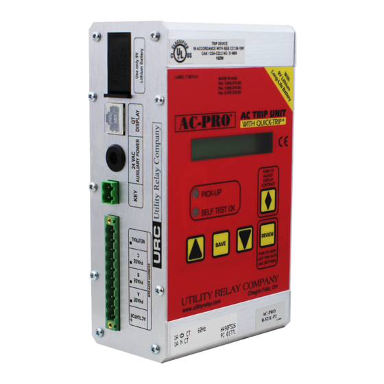
Page 7: Ac-Pro Front View
® 5.0 AC-PRO Front View The front view of the horizontal version of the AC-PRO trip unit is shown in Figure 5.0-1. The front view of a vertical version of the AC-PRO is shown in Figure 5.0-2. Battery Wiring Harness... -
Page 8: Character Display
Utility Relay Company 5.1 16 Character Display 5.6 DOWN Push Button A 16-character dot matrix liquid crystal display (LCD) Use this push button to decrease the setting values during provides information to the user. commissioning. When the “DOWN” push button is held... -
Page 9: Quick-Trip System
2. QUICK-TRIP Display with a “QUICK-TRIP ON“ LED. If an older Pro-Display without the “QUICK-TRIP ON” 3. Padlocking selector switch mounted near the LED is plugged into an AC-PRO with QUICK-TRIP, the QUICK-TRIP Display that is used to turn QUICK-TRIP QUICK-TRIP settings will always be on. -
Page 10: Quick-Trip Installation
(2) 10-32 hex nuts, flat washers breaker cubicle door. and lock washers. 5. Connect the QUICK-TRIP Display to the AC-PRO trip To install the QUICK-TRIP Display: unit by plugging one end of the shielded modular cable provided into the jack on the back of the QUICK- Find a suitable location on the cubicle door and mark TRIP Display. -
Page 11: Quick-Trip & Pro-Display Operation
4 lower push buttons on the face of the unit are pressed for 30 seconds. It is best to have all the desired settings Before the AC-PRO trip unit is put into service, it must first readily available before commissioning the unit when using be commissioned so it will function. -
Page 12: Ct Rating
Utility Relay Company 7.3 CT Rating current 6 times the LT Pick-Up setting is applied. See the time-current curves in Figure 18.2. After the security key is connected, the following will be displayed: Press and hold the "UP" or "DOWN" push button as required until the correct LT Delay setting is displayed. -
Page 13: Instantaneous (I) Pick-Up Setting
® ® AC-PRO With QUICK-TRIP Instruction Manual www.utilityrelay.com 7.9 Instantaneous (I) Pick-Up Setting 7.12 Ground Fault (GF) I The following will be displayed: The I²T function adds a ramp to the GF delay if required for coordination purposes as shown in the Ground Fault TCC in... -
Page 14: Phase Unbalance (U/B) Delay
7.15 Address amps. The minimum QT GF Pick-Up setting is 20% of the CT rating This setting applies only to AC-PRO trip units with the with 10 amp steps (1 amp steps for 50 to 200 amp CTs). communication option and will not be displayed on non- The maximum value is 200% of the CT rating or 1200 amps, communicating trip units. -
Page 15: Thermal Memory
AC-PRO With QUICK-TRIP Instruction Manual www.utilityrelay.com 7.19 Thermal Memory 7.20 Exit Procedure The AC-PRO trip unit has a Thermal Memory feature for the The following will be displayed: following protective functions: Long Time (LT) SAVE IF DONE Short Time (ST) -
Page 16: Changing Settings
Utility Relay Company 8.0 Changing Settings **** IMPORTANT **** While it is possible to make changes to the settings with the breaker in service, it is strongly recommended that the breaker must be removed from service while making these changes since the breaker is energized and the trip unit will not provide protection during a small part of this process. -
Page 17: Last Trip Data Recall
9.0 Last Trip Data Recall If the “REVIEW” button is pushed again and held down for The AC-PRO has an especially useful last trip data recall longer than 2 seconds, each type of trip is displayed along and trip counter feature. -
Page 18: Normal Operation
Breaker Current Less than about 8% of CT Rating: A "primary injection" test is recommended as the final test of the AC-PRO retrofit. With all phase currents less than about 8%, the trip unit is not receiving enough energy from the CTs to operate and... -
Page 19: St Trip Test
"C" a GF trip will not occur. To test QT GF the QUICK-TRIP Display must be connected to the AC-PRO trip unit and the QUICK-TRIP ON-OFF selector switch must also be connected as shown in Figure 6.0-1. With QT GF Pick-Up set to the required value and the... -
Page 20: Qt I Trip Test
To test QT I the QUICK-TRIP Display must be connected to After completing the primary or secondary injection tests, it is the AC-PRO trip unit and the QUICK-TRIP ON-OFF selector important to erase the last trip data from the memory of the switch must also be connected as shown in Figure 6.0-1. -
Page 21: Secondary Injection Testing
AC-PRO trip units. To secondary injection test the AC-PRO trip unit with this type of test set, the AC-PRO trip unit must be isolated from This test set can test 60Hz, 50Hz, 40Hz and 25Hz the test set ground. -
Page 22: Lt Delay Testing Chart
Utility Relay Company 12.3 LT Delay Testing Chart This chart provides trip times in Seconds for the LT Delay The Time-Current Curves in Figure 18.2 along with the settings at 3.0X, 4.0X and 6.0X where “X” is in multiples of equations in Section 15 can be used to determine the trip the LT Pick-Up setting. -
Page 23: Ratings
14.0 Warranty I²T = Constant A conditional 2-year warranty is offered with each AC-PRO trip unit and Pro-Display. Where: I is current in amps T is time to trip in seconds (center of the band) Contact Utility Relay Company for full details. -
Page 24: Lt Trip Time
Utility Relay Company 15.1 LT Trip Time 15.2 ST Trip Time For overload currents, the "I²T = Constant" equation can be With I T off or for currents greater than 10 X LT Pick-Up restated as follows: Setting, the ST trip time is a constant equal to the ST Time Band setting. -
Page 25: Gf Trip Time
2) Calculate "X " where = ground fault current MEMORY ERROR CT Rating 3) Solve the equation: All push buttons are disabled. The micro-controller must be trip time(sec) = TBC replaced. Contact Utility Relay Company for more information. Page 21... -
Page 26: Battery Replacement
Utility Relay Company 17.0 Battery Replacement Older AC-PRO trip units did not have a battery cover. To For best performance, replace the battery with the following replace the battery on these AC-PROs, the top of the trip 9-volt lithium battery: unit must be removed. -
Page 27: Typical Wiring Diagram
® ® AC-PRO With QUICK-TRIP Instruction Manual www.utilityrelay.com Neutral CT Only for 4-Wire system Phase CTs with GF "ON" LINE LINE LINE LINE Phase A Phase B Phase C Neutral LOAD LOAD LOAD LOAD Optional Actuator To QT Display (Optional) - Page 28 Utility Relay Company INTENTIONALLY LEFT BLANK Page 24...
-
Page 29: Overload Tcc
® ® AC-PRO With QUICK-TRIP Instruction Manual www.utilityrelay.com AC−PRO Trip Unit 1000 1000 LT Delay Long Time (LT) Pick−Up 0.5 sec. steps 5A steps 2.0 to 30.0 sec. 20% to 100% of CT Rating @ 600% LT Pick−Up (50A steps for CTs > 5000A) (0.5A steps for CTs <... - Page 30 Utility Relay Company INTENTIONALLY LEFT BLANK Page 26...
-
Page 31: U/B & Gf Tcc
® ® AC-PRO With QUICK-TRIP Instruction Manual www.utilityrelay.com 40% 60% 100% 100% 200% 1000 1000 Unballance (U/B) Pick−Up OFF & 5% steps from 20% to 50% 50% U/B 20% GF Pick−Up Pick−Up Ground Fault (GF) Pick−Up OFF & 10A steps... - Page 32 Utility Relay Company INTENTIONALLY LEFT BLANK Page 28...
-
Page 33: Quick-Trip ® Gf & I Tcc
® ® AC-PRO With QUICK-TRIP Instruction Manual www.utilityrelay.com 40% 60% 100% 200% 100% 200% 1000 Minimum possible Instantaneous (I) Pick−Up Quick−Trip Instantaneous (QT I) Pick−Up Allowance for 3−Phase power−up time 20% QT GF Pick−Up Quick−Trip Ground Fault Pick−Up (QT GF Pick−Up) OFF &... - Page 34 Utility Relay Company INTENTIONALLY LEFT BLANK Page 30...
Need help?
Do you have a question about the AC-PRO and is the answer not in the manual?
Questions and answers