Table of Contents
Advertisement
Quick Links
Advertisement
Table of Contents

Related Manuals for Kongsberg 3710

Summary of Contents for Kongsberg 3710
- Page 1 Instruction manual 3710 DGNSS Receiver Differential GNSS Receiver...
- Page 3 Kongsberg 3710 DGNSS Receiver Differential GNSS Receiver Instruction Manual G212-03/1.0 October 2013 © Kongsberg Seatex AS...
- Page 4 The information contained in this document remains the sole property of Kongsberg Seatex AS. No part of this document may be copied or reproduced in any form or by any means, and the information contained within it is not to be communicated to a third party, without the prior written consent of Kongsberg Seatex AS.
-
Page 5: Table Of Contents
Instruction Manual Table of contents Glossary........................6 INTRODUCTION............... 9 About the reader .....................9 Notations used in this manual.................9 Product restrictions....................9 1.3.1 Restrictions in guarantee ................9 1.3.2 Restrictions in use..................10 Disposal ........................10 Equipment handling....................10 PRODUCT DESCRIPTION..........12 Purpose and applications ..................12 System features.....................13 DGNSS processing....................14 2.3.1... - Page 6 Kongsberg 3710 DGNSS Receiver INSTALLATION .............. 22 Logistics .......................22 Location of system parts..................22 4.2.1 DGNSS antenna..................22 4.2.2 Receiver Unit ..................26 Antenna and cable installation................26 4.3.1 DGNSS antenna and cable installation............27 Electrical installation ....................28 CONFIGURATION............30 Navigation ......................30 LED indicators Receiver Unit ................30...
- Page 7 Instruction Manual 6.9.4 3710 SW version ..................47 6.9.5 Fugro Library version................47 MAINTENANCE .............. 48 Periodic maintenance....................48 7.1.1 Software upgrades................... 48 7.1.2 Cleaning of air inlet................. 48 Repairs and modifications ..................49 7.2.1 Exchange of antenna cable................ 49 7.2.2 Exchange of antenna ................49 7.2.3...
-
Page 8: Glossary
Kongsberg 3710 DGNSS Receiver Glossary Abbreviations Communauté Européenne Counter Electro-magnetic Force CEMP Carrier-to-noise ratio Carrier-to-normalized noise ratio C/N0 DGNSS Differential Global Navigation Satellite System DGPS Differential GPS DHCP Dynamic host configuration protocol Dilution of positioning Differential positioning system European Norm... - Page 9 Instruction Manual WEEE Waste electrical and electronic equipment WGS84 World Geodetic System of 1984 Virtual base station G212-03/1.0...
- Page 10 Kongsberg 3710 DGNSS Receiver G212-03/1.0...
-
Page 11: Introduction
1 Introduction 1.1 About the reader This manual describes how to install, configure and operate the 3710 DGNSS Receiver. It provides guidelines for using the LCD display to view and configure DGNSS corrections and communication operating parameters. The manual also provides... -
Page 12: Restrictions In Use
Kongsberg 3710 DGNSS Receiver The liability of Kongsberg Seatex AS is limited to repair of this system only under the given terms and conditions stated in the sales documents. Consequential damages such as customer's loss of profit or damage to other systems traceable back to this system's malfunctions, are excluded. - Page 13 Introduction • The storage area's mean temperature must not be lower than – 20 ºC and not warmer than + 70 ºC. • Once unpacked, the equipment must be kept in a dry, non-condensing atmosphere, free from corrosive agents and isolated from sources of vibration. G212-03/1.0...
-
Page 14: Product Description
Kongsberg 3710 DGNSS Receiver 2 Product description This chapter describes the 3710 DGNSS Receiver, and gives an overview of DGNSS operation. 2.1 Purpose and applications The 3710 DGNSS Receiver is a high-performance DGNSS receiver and a component of the Fugro worldwide DGNSS Service. -
Page 15: System Features
Available in South America, West Africa, Europe, the Middle East and upon request in other areas. The 3710 DGNSS Receiver has a built-in display for easy system configuration and status monitoring. 2.2 System features The system comprises the following features: •... -
Page 16: Dgnss Processing
Kongsberg 3710 DGNSS Receiver 2.3 DGNSS processing The 3710 DGNSS Receiver comprises a software defined radio (SDR) signal processing core with advanced algorithms and true parallel processing of up to two DGNSS satellite signals and one DGNSS Ethernet signal (NTRIP format). DGNSS corrections from different sources are combined by the unique multiplexing capability. -
Page 17: System Components
Product description Figure 1 Differential GNSS (DGNSS) concept System components The 3710 DGNSS Receiver exists with two different solutions, Spotbeam or Inmarsat, which have the following components. Spotbeam solution • Receiver Unit • Spotbeam antenna (DGNSS) • Spotbeam antenna mounting bracket •... -
Page 18: Receiver Unit
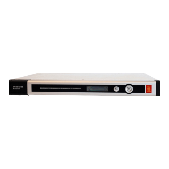
Kongsberg 3710 DGNSS Receiver 2.5 Receiver Unit The Receiver Unit is designed to fit standard 19-inch racks and is typically installed on the bridge or in the instrument room. The unit comprises the following main parts: • Receiver Unit • Power supply •... -
Page 19: Technical Specifications
Technical specifications 3 Technical specifications 3.1 Physical dimensions 3.1.1 Receiver Unit Height 43.65 mm (1U) Width 485 mm (19”) including mounting bracket Depth 350 mm (with connector and front panel) Weight 3.0 kg Colour Front anodized natural 3.1.2 DGNSS antenna Type AD430–3141 96 mm... -
Page 20: Dgnss Antenna
Kongsberg 3710 DGNSS Receiver 3.2.2 DGNSS antenna Type AD430–3141 Voltage 12V DC from Receiver Unit 3.3 Environmental specifications 3.3.1 Receiver Unit Enclosure material Aluminium -15 °C to +55 °C Operating temperature range Recommended operating Room temperature (+20 °C) temperature Storage temperature -20 °C to +70 °C... -
Page 21: Product Safety
Technical specifications 3.5 Product safety 3.5.1 Receiver Unit Electrical safety (LVD) IEC 60950-1/EN 60950-1 Electromagnetic compatibility IEC-60945/EN60945 (immunity/radiation) Vibration IEC-60945/EN60945 3.6 Radio frequencies 3.6.1 DGNSS antenna Type AD430–3141 Frequency 1525 to 1559 MHz 3.7 Data outputs 3.7.1 Receiver Unit Message format Multiplexed (MUX) correction format Message type Multiplexed correction data output with status... -
Page 22: Rear Interfaces Receiver Unit
Kongsberg 3710 DGNSS Receiver Type Connector Comments USB-A For data logging and software upgrade 3.8.2 Rear interfaces Receiver Unit The rear panel of the Receiver Unit contains communication interface ports for interfacing external equipment, and DGNSS signal input. Connector Type... - Page 23 Technical specifications 3.8.3.2 Ethernet connection The Receiver Unit has the following LAN and connection possibilities. • LAN at the rear To connect this LAN to a network, a straight-through twisted pair (TP) cable with RJ-45 connectors must be used. A straight-through cable is one where the pins of one connector are connected to the same pins of the other connector.
-
Page 24: Installation
Kongsberg 3710 DGNSS Receiver 4 Installation This chapter covers the installation of the Receiver Unit and the DGNSS antenna. The installation includes: • Location of the system parts • Installation of the Receiver Unit • Installation of the DGNSS antenna and cable (for Spotbeam solution) •... - Page 25 Installation If the antenna is installed in a poor location, it can suffer from masking, multipath or interference from other radio sources which can affect the position performance. Masking The GNSS antenna should have an unobstructed line of sight to the sky. The signals from the satellite propagate by line-of-sight, which means that if the antenna cannot see the satellite, the reception will be severely impaired, if it occurs at all.
- Page 26 Kongsberg 3710 DGNSS Receiver Figure 3 Bad antenna location, typically masking situation Multipath Inappropriate location of the antenna can result in the antenna receiving reflections of the incoming signal as well as the signal itself (multipath). The reflected multipath signal takes a longer path than the direct signal, introducing an error into the position calculation.
- Page 27 Installation Interference from other radiating sources Interference can be caused by close proximity to other radiating sources. Installing DGNSS antennas in close proximity to satellite communication systems operating in or nearby DGNSS frequency bands (1.525 to 1.559 GHz) should be avoided (i.e. Sat C, Iridium).
-
Page 28: Receiver Unit
Kongsberg 3710 DGNSS Receiver During installation, comprehensive tests should be carried out for potential interference by conducting transmissions from each RF source for extended periods, individually and simultaneously. Antenna location Antenna location is critical to system performance. When installing the antenna, note the following: •... -
Page 29: Dgnss Antenna And Cable Installation
Installation It should also be noted that a too powerful signal may cause saturation of receiving circuitry in shorter cable runs, making it necessary to use signal attenuators or cables with higher attenuation levels. Sharp bends, kinks and unnecessary connections should be avoided. External connections should be appropriately treated with self-amalgamating tape other preparations to keep out water. -
Page 30: Electrical Installation
Kongsberg 3710 DGNSS Receiver Wrap outdoor cable connections with waterproof self-vulcanising tape. An alternate way of waterproofing is to use heat shrink hose with glue. The hose should cover the whole connector and part of the cable. Secure the cable to the mast every one to three metres with clamps or bands. - Page 31 Installation When the software is up and running, the left LED indicator turns green. The installation is now completed and the setup of the configuration parameters can continue through the display in the front. G212-03/1.0...
-
Page 32: Configuration
Kongsberg 3710 DGNSS Receiver 5 Configuration The Receiver Unit includes an integrated LCD display and keypad for accessing the internal menu system. Use the menus and screens to configure the system and review the system status. Because the display only provides 2 lines of 16 characters, the Receiver Unit uses a number of menus and submenus to access the status and configuration screens. - Page 33 Configuration From the front view of the unit, the LEDs will have the following information: The LED to the left indicates power and software status, the second to the left indicates satellite 1 status, while the third to the left indicates satellite 2 status and the fourth to the left indicates the NTRIP status.
- Page 34 Kongsberg 3710 DGNSS Receiver The LED is red if all of the last 100 data packets are bad, or no data or lock is obtained during the last 120 seconds. Satellite 2 LED The LED is constantly green, if there are available good data on the satellite link.
-
Page 35: Operation
Operation 6 Operation This chapter describes the menu system and the displays in the 3710 DGNSS Receiver. 6.1 Getting started 6.1.1 Receiver Unit configuration How to configure the Receiver Unit Ensure that the power cable, the network and the antenna are connected. -
Page 36: Main Menu
Kongsberg 3710 DGNSS Receiver Press the power switch. The Receiver Unit will shut down. 6.3 Main menu The menu structure is divided into main menu items and each main menu item has a status and a configuration submenu. The only exception is the... -
Page 37: Home Main Menu
Operation 6.4 HOME main menu menu item has three different views, which HOME the receiver alternates between. This menu provides the user with all the information needed to verify a correct operation and to obtain a valid subscription. The HOME menu is the default menu item. -
Page 38: Satellite Information
Kongsberg 3710 DGNSS Receiver 6.4.1 Satellite information • Line 1 – The name on satellite 1 is displayed before the tracking information of the satellite. If no satellite list is available, it will display No Name • Line 2 – The name on satellite 2 is displayed before the tracking information of the satellite. -
Page 39: Satellite 1/Satellite 2 Main Menu
Operation 6.5 Satellite 1/Satellite 2 main menu and the main menu items are identical in structure, and show the Satellite 1 Satellite 2 user settings for satellite 1 and satellite 2 under the submenu. In the Satellite 1/2 Status submenu, the user can select which satellite link to connect to Satellite 1/2 Configuration or he can manually configure frequency and symbol rate of the preferred satellite link. -
Page 40: Satellite1/Satellite 2 Configuration
Kongsberg 3710 DGNSS Receiver Bars filled C/N [dB] 5 bars 5 – 6 6 bars > 6 6.5.1.2 Satellite symbol rate Displays the rate at which the tracked DGNSS satellite data are modulated to the carrier wave. 6.5.1.3 Good counts Displays the percentage of good data packets for the last two hours. -
Page 41: Ntrip Status
Operation 6.6.1 NTRIP status 6.6.1.1 NTRIP source Shows the preferred mount point from which to obtain data. Select from items in the list, which is received when connected to the NTRIP server. It will only be shown if NTRIP is enabled. 6.6.1.2 NTRIP host Shows the NTRIP host IP address. -
Page 42: Ntrip Configuration
Kongsberg 3710 DGNSS Receiver 6.6.1.4 Good counts Displays the percentage of good data packets for the last two hours. The total number of data packets for the last x minutes is also shown. The time counter will reset at 120 minutes, and start a new calculation. -
Page 43: Network Main Menu
Operation 6.7 Network main menu main menu item shows the user settings for the network configuration under Network the status submenu. From the submenu the user can select how Network Configuration to configure the output of the DGNSS correction data on Ethernet. Each receiver can be configured with one Ethernet port, set up as output of up to three DGNSS correction sources simultaneously. -
Page 44: Network Configuration
Kongsberg 3710 DGNSS Receiver 6.7.1.3 Gateway Shows the gateway of the Receiver Unit. 6.7.1.4 Output port Shows the output network port of the Receiver Unit. 6.7.2 Network configuration 6.7.2.1 Network setup Select the network configuration from nine predefined network settings, manual configuration or factory default. -
Page 45: Control Main Menu
Operation 6.7.2.2 Set IP address Select the IP address of the unit. Only shown if Manual selected under the menu element. Network configuration 6.7.2.3 Set netmask Select the netmask of the unit. Only shown if Manual selected under the menu element. Network configuration 6.7.2.4 Gateway Select the gateway of the unit. -
Page 46: Restart Unit
Kongsberg 3710 DGNSS Receiver 6.8.1 Restart unit It is possible to restart the unit from inside the menu. 6.8.2 Factory reset Load the factory default settings. Select between will restore Seatex Fugro Seatex all configuration to the factory default while will delete the subscription on the unit. -
Page 47: Antenna Power
Operation 6.8.4 Antenna power Read the antenna connector voltage and current. It is also possible to turn the antenna power on or off. Note After a short circuit of the antenna power, the voltage is turned off and the status shows . -
Page 48: Logging
Kongsberg 3710 DGNSS Receiver 6.8.7 Logging Save tracking data during operation for later processing or software upgrades of the unit. Note A USB storage device must be inserted in front of the unit to enable data storage. 6.9 About main menu main menu item contains information about the Receiver Unit. -
Page 49: Subscription Type
Shows the elements which the unit is subscribed to. 6.9.3 Expiry date Shows the date when the current subscription ends. 6.9.4 3710 SW version Shows the SW version of the current version running in the unit. 6.9.5 Fugro Library version Shows the version of the Fugro Library running on the current unit. -
Page 50: Maintenance
7.1 Periodic maintenance 7.1.1 Software upgrades Kongsberg Seatex AS will regularly offer software upgrades for the system with improvements and new functionality. It is up to the user to decide whether he will upgrade his unit to the latest version. -
Page 51: Repairs And Modifications
Maintenance Cover and filter removed Filter cover in place 7.2 Repairs and modifications 7.2.1 Exchange of antenna cable How to change antenna cable Caution If the antenna cable is attached to the unit, do not attach the antenna cable to the antenna with the Receiver Unit powered on. If the antenna cable is short-circuited with power on, the receiver within the unit will be damaged. -
Page 52: Repair Of Receiver Unit
Kongsberg Seatex AS qualified personnel. A failed unit should be shipped back to Kongsberg Seatex AS or other agreed service point for repair. 7.2.4... -
Page 53: External Output Problems
Check the serial lines and cable connectors for mechanical damage. Check that the connectors are connected to the correct output ports both on the Kongsberg Seatex AS equipment and on the external equipment. If the cable and connectors are OK, check that the external output configuration of the Receiver Unit is set up correctly. -
Page 54: Mechanical Drawings
Kongsberg 3710 DGNSS Receiver 8 Mechanical drawings This chapter contains outline drawings showing mechanical dimensions of the Receiver Unit. Note The drawings are not to scale. To-scale drawings are available on request. G212-03/1.0... -
Page 55: Receiver Unit Dimensions
Mechanical drawings 8.1 Receiver Unit dimensions G212-03/1.0... -
Page 56: References
Kongsberg 3710 DGNSS Receiver 9 References Reference documents NMEA 0183 Standard for Interfacing Marine Electronic Devices, Version 3.00 RTCM Recommended Standards for Differential Navstar GPS/GLONASS Service, Version 2.3 G212-03/1.0... -
Page 57: Coax Connector Installation
Appendix A Coax connector installation Appendix A Coax connector installation The connector consists of two parts: the connector head and the cable entry. The instructions below are an excerpt from Huber+Suhner assembly instruction, DOC-0000179418, rev. C, March 2008. G212-03/1.0... - Page 58 Kongsberg 3710 DGNSS Receiver G212-03/1.0...
- Page 59 Appendix A Coax connector installation G212-03/1.0...
- Page 60 Kongsberg 3710 DGNSS Receiver G212-03/1.0...
- Page 61 Appendix A Coax connector installation G212-03/1.0...
-
Page 62: ½" Coax Cable Specifications
Kongsberg 3710 DGNSS Receiver Appendix B ½" coax cable specifications Excerpt from Draka data sheet dated 26/09/2006. G212-03/1.0... - Page 63 Appendix B ½" coax cable specifications G212-03/1.0...
-
Page 64: Dgnss Antenna
Kongsberg 3710 DGNSS Receiver Appendix C DGNSS antenna General arrangement drawing for the AD 430 antenna with mounting bracket. The diameter for the ground plane is 150 mm (6 inches). Three M4 fixing holes are provided on the ground plane for an optional extension disc. -
Page 65: Receiver Unit And Processing Unit Configuration
Receiver Unit and Processing Unit configuration The Receiver Unit can be used together with a variety of Kongsberg Seatex AS Processing Units, for example DPS, DARPS and Seapath. The Receiver Unit and the Processing Unit must be connected via a network switch. If communication with external networks is required, an additional router must be connected and configured. - Page 66 Kongsberg 3710 DGNSS Receiver For each Receiver Unit used in a Processing Unit, a configuration in the Processing Unit must be performed. The configuration is carried out in the NAVEngine Configuration view in the Processing Unit. For each interface connected, serial line and/or Ethernet, one DGNSS link must be set up.
- Page 67 I/O properties Broadcast LAN 2 Local interface drop-down list. Type the local port number in the box as selected on Local port 3710 DGNSS receiver Under , select from the DGNSS link properties 3710 DGNSS receiver Interface drop-down list and select from the drop-down list.
- Page 68 Kongsberg 3710 DGNSS Receiver Related topics • Router on page 67 G212-03/1.0...
-
Page 69: Router
The router should be setup and configured before connected to the internal network. The router must be configured with one LAN IP address for use with Kongsberg Seatex AS equipment and one WAN IP address for use with external equipment. The LAN IP address used in the Kongsberg Seatex AS internal network shall be 192.168.1.1. - Page 70 Connect the router to the switch. Note The router is configured to have LAN IP address 192.168.1.1 by Kongsberg Seatex AS. If no contact on this address, try to gain contact on the default LAN IP address which is 192.168.127.254.
- Page 71 Appendix E Router G212-03/1.0...
- Page 72 © 2013 Kongsberg Seatex...
- Page 74 © Kongsberg Seatex AS...
Need help?
Do you have a question about the 3710 and is the answer not in the manual?
Questions and answers