Record Power PT260 Operating Manual And Service Instructions
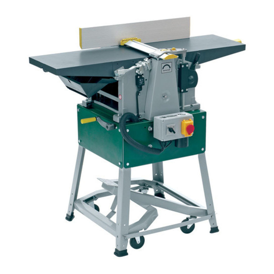
Planer & thicknesser woodworking machine
Hide thumbs
Also See for PT260:
- Original instruction manual (36 pages) ,
- Instruction manual (14 pages)

Related Manuals for Record Power PT260


Summary of Contents for Record Power PT260
- Page 1 PLANER &THICKNESSER WOODWORKING MACHINE PT260 USER’S OPERATING MANUAL & SERVICE INSTRUCTIONS CAUTION Read the instruction manual before using the appliance...
-
Page 2: Use Of The Machine
Foreword These instructions have been created by the device manufacturer and are an integral part of the machine delivery. They contain basic information for qualified operating staff and describe the environment and manners of the machine use for which it has been designed, and also contain any information necessary for the correct and safe operation. -
Page 3: Working Environment
Working environment The machine must be operated in a workshop environment the temperature of which does not exceed +40℃and does not drop below +5℃. The relative humidity of ambient is from 30% to 95%, non-condensing. The height above the sea level is up to 1000 m. Storage and transportation temperature: -25~55℃... - Page 4 - If you have any doubts on correctness of your procedure, contact a responsible person. - Do not neglect performance of regular inspections in accordance with the instructions for use. - Check and make sure that no disturbances occur on the machine caused by the user. - After the work is finished, adjust the machine so that it is ready for another series of operations.
-
Page 5: Safety Regulations For Maintenance
socket. - Do not remove or interfere otherwise in safety devices such as covers, limit switches. - While handling parts above your possibilities, ask for helps from a qualified person. - It is not recommended to work on the machine during a storm. Safety regulations for maintenance Maintenance and repair must be performed by a qualified person. -
Page 6: Transport And Storage
intensity 500 lux. - Never put any tools or any other objects on working tables or covers. - Always keep the working area clean and tidy. Transport and storage Transport and storage While transporting or handling the machine, be most careful and let this activity be done by qualified personnel especially trained for this kind of activity. -
Page 7: Features And Terminology
Feeding speed m/min Motor power output Specifications concerning noise of the device Level of noise A in the place of operation (LpAeq) No-load =81.7 dB(A) Load =89.5 dB(A) Level of acoustic power A (LWA) No-load = 94.5 dB(A) Load = 103 dB(A) Operating conditions for noise measurement comply with annex B of ISO 7960. -
Page 8: Electrical Connection
use solvents on plastic parts. Unpacking 1. Remove all contents from the shipping carton. Do not discard the carton or packing material until the machine is set up and running satisfactorily. 2. Inspect the contents for shipping damage. Report damage, if any, to your distributor. Tools Required for Assembly 1 Accurate Straight Edge (approximately 2 ft) 1 Cross-point Screwdriver... - Page 9 Table is heavy. Use care when raising. Failure to comply may cause serious injury. When raised, the table should be in the vertical position as shown in C, Fig. 3. The latch (E, Fig. 3) should be engaged, preventing the table from an accidental forward fall. 3.
-
Page 10: Planer Controls And Adjustments
Power Once a properly rated plug is connected, plug power cord into outlet. Press the green on button (A, Fig. 4) to start. Press the red off button (B, Fig. 4) to stop. Planer Controls and Adjustments Referring to Figure 5: Power Feed Placing the planer power feed handle (D) in the up position turns the planer power feed on (see arrow). -
Page 11: Jointer Controls And Adjustments
planer table (C) in its selected position. Turn the table lock (E) counterclockwise to release and permit table adjustment. Table Height Adjustment The planer table height is set as follows: 1. Unlock the table lock (E). 2. Rotate the height adjustment handwheel (F) clockwise to raise the planer table (C), counterclockwise to lower. - Page 12 backward (C) across the width (W) of the table. It also tilts up to 45 degrees backwards (D). Loosen the lock knob (J), slide the guard into position, then tighten the lock knob. To slide fence forward or backward: When edge jointing, the fence assembly should periodically be moved to different positions to...
-
Page 13: Coplanar Alignment
These alignments are explained below. Disconnect machine from power source before making any adjustments. Failure to comply may cause serious injury. Coplanar Alignment Definition of coplanar When the infeed table is set to the same level as the outfeed table and together both tables form a "perfect"... - Page 14 If alignment is required as determined in the previous section, proceed as follows: Disconnect machine from power source before making any adjustments. Failure to comply may cause serious injury. 1. Disconnect power from machine. 2. Unlock both cabinet lock handles (A2). 3.
- Page 15 Setting Cutterhead Knives Before performing any adjustments in this section, the infeed and outfeed tables must Important: be coplanar. Cutterhead knives are dangerously sharp! Use extreme caution when inspecting, removing, sharpening or replacing knives into the cutterhead. Failure to comply may cause serious injury 1.
-
Page 16: Replacing Cutter Knives
the infeed table (G). 7. Adjust the blade height by turning jack screws (D) upon which the blades rest. To lower the blade, turn the screw clockwise. To raise, turn the screw counter-clockwise. 8. When the blade is at the proper height, alternately tighten the five gib lock screws(A). Repeat steps 4 –... - Page 17 2. Remove two button head socket screws (C) and upper back panel (D). 3. Remove four button head socket screws (O) and lower back panel (P). Cutterhead Drive Belt Replacement 4. Loosen four motor mount screws (L). Lift the motor and rest it in the horizontal slot side of the motor mount opening.
-
Page 18: Basic Operations
the factory and no further adjustment should be needed. If your machine is planing a taper, first check to see if the knives are properly adjusted in the cutterhead (see Setting Cutterhead Knives on page 14) and make adjustments if necessary. After the knives are confirmed to be properly set, check to see if the work table is set parallel to the cutterhead as follows. -
Page 19: Changing Mode Of Operation
Investigate and correct the source of any problems before further operation. DO NOT attempt to investigate or adjust the planer while it is running. Wait until the planer is turned off, unplugged and all working parts have come to a complete standstill. - Page 20 Direction of Grain Avoid feeding work into the jointer against the grain (Figure 18). This may result in chipped and splintered edges. Feed with the grain to obtain a smooth surface, as shown in Figure 19. Jointing Jointing (or edging) is the process of creating a finished, flat edge surface that is suitable for joinery or finishing (Figure 20).
-
Page 21: Planer Operations
Beveling Beveling an edge is the same operation as edge jointing, except that the fence is tilted to a specified angle. Make certain material being beveled is over 12 inches long, more than 1/4 inch thick and 1 inch wide. To bevel: 1. - Page 22 1/8”. The maximum thickness of wood that can be removed in one pass is 1/16” for planning operations on workpieces from 5-1/2” up to 12" wide. For optimum planning performance, the depth of cut should be less than 1/16”. The board should be planed with shallow cuts until the work has a level side. Once a level surface has been created, flip the lumber and create parallel sides.
-
Page 23: Maintenance
1. Position the workpiece with the face to be planed on top. 2. Turn the planer on. 3. Turn the power feed on. 4. Rest the board end on the infeed roller plate and direct the board into the planer. 5. - Page 24 3. To protect the infeed table from scratches, partially cover the sharpening stone with paper (Figure 22). 4. Lay the stone on the infeed table. 5. Lower the infeed table and turn the cutterhead by turning the cutterhead pulley. The infeed table height is set properly when the stone's surface is flush with the knife bevel. 6.
-
Page 25: Troubleshooting
Troubleshooting Performance Troubleshooting – Jointer... -
Page 26: Performance Troubleshooting - Planer
Performance Troubleshooting – Planer... -
Page 27: Mechanical Troubleshooting - Planer/Jointer
Mechanical Troubleshooting – Planer/Jointer... - Page 29 31 ..JPT310-031 ....Big Cam Wheel for Safty Switch ............1 32 ..JPT310-032 ....Hex. Socket Set Screw ......M6X8 ........2 33 ..PT260-033 ....Cutterblock Guard Profile W/Cap ............1 34 ..JPT310-034 ....Hex. Socket Set Screw ................. 8 35 ..
- Page 31 70 ..JPT310-070 ....Special Screw for Locking Bar ............15 71 ..PT260-071 ....Cutter Block ..................1 .... PT260-071CBA..... Cutter Block Complete Assembly (#68, #69, #70, #71) ......1 72 ..JPT310-072 ....Pan Head Screw ........M6X12 ........4 73 ..
- Page 33 160 ..JPT310-160 ....Pan Head Screw ........M6X12 ........2 161 ..JPT310-161 ....Washer ..........H6 ........... 7 162 ..PT260-162 ....Front Cover ..................1 163 ..JPT310-163 ....Handle ....................1 164 ..JPT310-164 ....Lock Knob .................... 4 165 ..
- Page 35 PT-260 Infeed Table Assembly Index Part Description Size 182 ..JPT310-182 ....Outfeed Table Bracket Shaft ..............1 184 ..JPT310-184 ....Infeed Table Bracket Right ..... M8X60 ........2 190 ..JPT310-190 ....Infeed Table Bracket Left ..............1 203 ..
- Page 37 241 ..JPT310-241 ....Hex. Bolt ..........M8X25 ........4 242 ..JPT310-242 ....Washer ..........H8 ........... 4 243 ..PT260-010E ....Motor 230/50/1 ..................1 .... PT260-010AE ....Motor 400/50/3 ..................1 244 ..JPT310-244 ....Washer ..........H8 ........... 4 245 ..
- Page 38 PT-260 Thickness Table Assembly...
- Page 39 329 ..JPT310-329 ....Washer ..........H8 ........... 2 330 ..JPT310-330 ....Thread Rob Bracket ................1 331 ..PT260-331 ....Column Support ..................1 333 ..JPT310-333 ....Hex. Socket Set Screw ......M8x20 ........5 335 ..
- Page 40 PT-260 Working Fence Assembly...
- Page 41 379 ..JPT310-379 ....Pan Head Sscrew ........M6X12 ........6 380 ..JPT310-380 ....Washer ..........H6 ........... 6 381 ..PT260-381 ....Cutterblock Cover ................. 1 382 ..JPT310-382 ....Lock Nut ..........M6 .......... 4 383 ..JPT310-383 ....Hex. Socket Cap Screw ......M6X10 ........4 384 ..
Need help?
Do you have a question about the PT260 and is the answer not in the manual?
Questions and answers