
Subscribe to Our Youtube Channel
Related Manuals for Leybold vacuum TURBO.DRIVE 400

Summary of Contents for Leybold vacuum TURBO.DRIVE 400
- Page 1 TURBO.DRIVE 400 Frequency Converter for Turbomolecular Pumps Operating Instructions 17200492_002_A5 Part Numbers 800073V0002 800073V0003 800073V0004 800073V0008 i v e...
-
Page 2: Table Of Contents
Operation at reduced current Changing the frequency dependent normal operation level Changing the maximum permissible run up time 45 3.10 Changing the start delay time 3.11 Selecting relay functions 3.12 Reading the error memory 17200492_002_A5 - 04/2011 - © Oerlikon Leybold Vacuum... - Page 3 Operating Instructions and follow the information so as to ensure optimum and safe working right from the start. The Oerlikon Leybold Vacuum TURBO.DRIVE 400 has been designed for safe and efficient operation when used properly and in accordance with these Operating Instructions.
-
Page 4: Important Safety Information
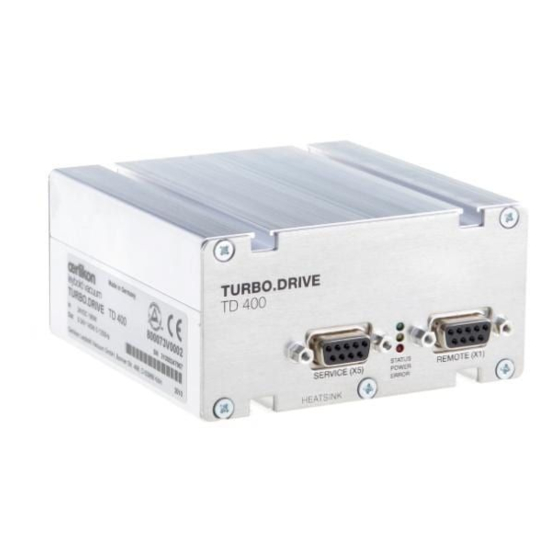
(green status LED off) and with the mains power switched off (yellow power LED off). Otherwise there is the risk of damaging the TURBO.DRIVE 400. 17200492_002_A5 - 04/2011 - © Oerlikon Leybold Vacuum... - Page 5 No error, no warning flashes: Warning is present, pump can be operated possibly with some restrictions Fault is present, pump stopped or can not be operated Fig. 1.1 TURBO.DRIVE 400, front and rear side 17200492_002_A5 - 04/2011 - © Oerlikon Leybold Vacuum...
- Page 6 TU R B O . D R I VE TD 400 Fig. 1.3 Front side of TURBO.DRIVE 400 with additional RS 485 interface USB connection TU R B O . D R I VE TD 400 (X106) Abb.
-
Page 7: Description
Description Description Design and function The TURBO.DRIVE 400 supplies power to the TW and SL series turbomolecular pumps and is used to control their operation. The TURBO.DRIVE 400 is either integrated in the pump or it is separate and linked to the pump by means of a connecting cable. -
Page 8: Technical Data
Contamination grade Temp. of the cooling surface 5 - 55 °C 5 - 50 °C For Part Nos. 800073V0004 ≤ 20 W Power consumption Type of protection IP 20 Weight, approx. 0.7 kg 17200492_002_A5 - 04/2011 - © Oerlikon Leybold Vacuum... - Page 9 27,6 18,5 HEAT SINK HEAT SINK * Profibus-Version 20 * Profibus version 20 79,0 41,0 TURBO.DRIVE TD 400 15,9 18,2 63,8 Fig. 1.5 Dimensional drawing for the frequency converter; dimensions in mm 17200492_002_A5 - 04/2011 - © Oerlikon Leybold Vacuum...
-
Page 10: Ordering Data
OEM power supply (with screw terminals) SITOP 24 V / 10 A (120/230 VAC / 50/60 Hz) 152 50 ■ supplies the TURBO.DRIVE 400 with 24 V DC ■ other power supplies on request 24 V DC cable (TURBO.DRIVE 400 – OEM power supply) - Page 11 Description Power supply unit - plug and play TURBO.POWER 300 800100V0002 ■ supplies the TURBO.DRIVE 400 with 24 V DC T 5 A ~ 250 V ■ plug & play cables 100 - 240 V AC ■ desktop unit or rack mountable T 5 A ~ 250 V TURBO.POWER 300...
- Page 12 Oerlikon Leybold Vacuum → Documentation → Download Software GSD file for Profibus DP upon request The software can also be downloaded from www.oerlikon.com in the menu Oerlikon Leybold Vacuum → Documentation → Download Software 17200492_002_A5 - 04/2011 - © Oerlikon Leybold Vacuum...
-
Page 13: Installation
The TURBO.DRIVE 400 supplies power to the TW series turbomolecular pumps and is used to control their opera- tion. The TURBO.DRIVE 400 is suited for operation of the follo- wing pumps: ■ TURBOVAC TW 70 H ■ TURBOVAC TW 220/150 S, TW 220/150/15 S, TW 400/300/25 S ■... -
Page 14: Operating Environment
At altitudes over 1000 m heat dissipation by the ambient air is impaired. Please con- sult us. If the TURBO.DRIVE 400 has been integrated in the pump, it is cooled by the pump. As to the cooling requirements for the separately fitted TURBO. -
Page 15: Mounting The Frequency Converter
Operation possible without additional cooling Motor current (Parameter 5) Fig. 2.1 Cooling requirements for the TURBO.DRIVE 400 when fitted separately Mounting the frequency converter The frequency converter may be affixed with the aid of the enclosed M4 sliding nuts. The bottom side of the frequency converter must be cooled sufficiently. -
Page 16: Connecting The Pump
Installation Connecting the pump In the case of a separately fitted TURBO.DRIVE 400 connect the pump using the connecting cable. The pump may be operated only with a suitable fre- NOTICE quency converter and suitable connecting cables. Route all cables so as to protect them from damage. - Page 17 24 V DC In the case of an integrated TURBO.DRIVE 400 the DC cable, connecting cable is omitted. with shielding, max. 20 m Fig. 2.3 Connecting the pump and the power supply 17200492_002_A5 - 04/2011 - © Oerlikon Leybold Vacuum...
- Page 18 Installation 17200492_002_A5 - 04/2011 - © Oerlikon Leybold Vacuum...
- Page 19 Installation 17200492_002_A5 - 04/2011 - © Oerlikon Leybold Vacuum...
- Page 20 Installation 17200492_002_A5 - 04/2011 - © Oerlikon Leybold Vacuum...
-
Page 21: Relay Status
Installation 17200492_002_A5 - 04/2011 - © Oerlikon Leybold Vacuum... -
Page 22: Operation
Installation Operation Start-up The TURBO.DRIVE 400 offers the possibility of gently run- ning in pumps which were not operated for a period bet- ween 6 and 12 months. For this set the parameter P119 “Bearing run-in function” to 1; thereafter start this function through the start command. -
Page 23: Interfaces
■ RS 485 C ■ Profibus DP ■ USB The TURBO.DRIVE 400 is configured through the parame- ters according to the parameter list. Pxxx denotes parame- ter value xxx. The PC software "TURBO.DRIVE Server" allows convenient access by the user to the parameters of the frequency con- verter. - Page 24 Adjust second function: P29 Set motor current thresh.: P27 Lowering the normal operation Normal operating mode is Reduce frequency threshold threshold attained faster, processes through P25 can be started faster 17200492_002_A5 - 04/2011 - © Oerlikon Leybold Vacuum...
- Page 25 Pin assignment for the socket at the frequency converter (female) SERVICE X5 1,4 and 6-9 are internally connected and must not be used. TURBO.DRIVE Shield SERVICE X5 9-pin IBM PC RS 232 interface Fig. 3.2 Providing a RS 232 connection 17200492_002_A5 - 04/2011 - © Oerlikon Leybold Vacuum...
-
Page 26: Rs 232 C Interface (Service X5)
Links for activation of the bus terminator 0,5 A, 24 V DC TxD/RxD + TxD/RxD – Fig. 3.3 Pin assignment for the socket at the frequency converter for RS 485 interface (male) 17200492_002_A5 - 04/2011 - © Oerlikon Leybold Vacuum... -
Page 27: Rs 485 Interface
(yellow power LED off) and then on again so as to enable the new address setting. Bus addresses over 15 can only be set via Parameter 37. Refer also to Operating Instructions GA 05.281 17200492_002_A5 - 04/2011 - © Oerlikon Leybold Vacuum... - Page 28 Operation 17200492_002_A5 - 04/2011 - © Oerlikon Leybold Vacuum...
-
Page 29: Profibus Dp
76131 Karlsruhe, Germany P/N: 4.072 www.profibus.com Upon request we shall be pleased to provide detailed infor- mation on the hardware and the protocol used for the data. Refer also to Operating Instructions GA 05.281 17200492_002_A5 - 04/2011 - © Oerlikon Leybold Vacuum... -
Page 30: Usb Interface (X106)
USB host with a current of approximately 15 mA. Via the protec- tion diode, separation with respect to 33 V is maintained. 17200492_002_A5 - 04/2011 - © Oerlikon Leybold Vacuum... -
Page 31: Parameter List
(P183). Pump type Setpoint frequency 1200 Setpoint of the rotor frequency Normal operation Setpoint of the frequency dependent normal operation level 17200492_002_A5 - 04/2011 - © Oerlikon Leybold Vacuum... - Page 32 Run in using the run-in sequence specified through the pump table without run-up time monitoring (a min at b Hz ….c min at d Hz…in total 4 stages for mechanical pumps) 17200492_002_A5 - 04/2011 - © Oerlikon Leybold Vacuum...
- Page 33 0,1 A Actual average intermediate circuit current current of the converter. 150 Standby frequency 1200 Standby operation frequency setpoint 151 Enable standby 0 = normal speed (P24); 1 = standby speed (P150) 17200492_002_A5 - 04/2011 - © Oerlikon Leybold Vacuum...
- Page 34 Value 0.0: Indefinite time delay. In this way a change of the control right is inhibited. Values 0.1 ..6553.5: A change in the control right corresponding to the setting of parameter 179 is only effected after the time span defined through parameter 182 has elapsed. 17200492_002_A5 - 04/2011 - © Oerlikon Leybold Vacuum...
- Page 35 Bit 0: Normal operation status Bit 1: Ready for switch on Bit 2: Speed is increasing Bit 3: Speed is dropping Bit 4: Generator operation Bit 5: Standby Bit 6: reserved Bit 7: reserved 17200492_002_A5 - 04/2011 - © Oerlikon Leybold Vacuum...
-
Page 36: Specific Parameter Data For The Pumps
1 TW 400/300/25S TW 250/200/40 TW 250S TW 70 H 1200 TW 290 H / TW 300 / TW 300 H 1000 SL 80 1200 – – SL 300 1000 – – 17200492_002_A5 - 04/2011 - © Oerlikon Leybold Vacuum... - Page 37 3600 5400 5400 TW 70 H 3600 5400 5400 TW 290 H / TW 300 / TW 300 H 3600 5400 5400 SL 80 3600 5400 5400 SL 300 3600 5400 5400 17200492_002_A5 - 04/2011 - © Oerlikon Leybold Vacuum...
-
Page 38: Warning Codes For Parameter 227
Ensure min. ambient tem- temperature permissible too low perature of 0°C warning motor tempe- Pump cooling too Reduce water cooling rature (warning high threshold) is not reached. 4, 5 not used Overspeed warning 17200492_002_A5 - 04/2011 - © Oerlikon Leybold Vacuum... - Page 39 P4 > Umax or DC power supply P4 < Umin voltage below 24V Mains voltage failure Fan voltage has failed 17200492_002_A5 - 04/2011 - © Oerlikon Leybold Vacuum...
-
Page 40: Switching On
The turbomolecular pump accelerates. The green LED flashes. When the pump reaches normal operation the green LED lights up permanently. After a mains power failure the pump can run up automati- cally once more. 17200492_002_A5 - 04/2011 - © Oerlikon Leybold Vacuum... -
Page 41: Shutting Down
■ apply a stop command via the interface. ■ for the power supply units offered or recommended by Oerlikon Leybold Vacuum switch off the DC voltage. After switching off, the green status LED will flash until the rotor of the turbomolecular pump is at standstill. This may take several minutes. -
Page 42: Setting Pumping Speed And Rotational Speed
Profibus in two ways: ■ by changing parameter 24 within the limits defined by parameters 19 and 18 or ■ by transfer as the main setpoint (for this also refer to VDI/VDE 3689). 17200492_002_A5 - 04/2011 - © Oerlikon Leybold Vacuum... -
Page 43: Operation At Reduced Current
Operation Operation at reduced current Not all applications require that the TURBO.DRIVE 400 be operated at its maximum current. Operation at reduced current will allow operation off a smaller power supply unit or to operate two or more turbomolecular pumps off a... -
Page 44: Changing The Frequency Dependent Normal
So as to retain the value saved for parameter 25 when switching the pump off, the parameter value needs to be saved permanently. For this enter any value (for example 1) for parameter 8. Thereafter changed parameters will be saved permanently. 17200492_002_A5 - 04/2011 - © Oerlikon Leybold Vacuum... -
Page 45: Changing The Maximum Permissible Run Up Time
So as to retain the value saved for parameter 32 when switching the pump off, the parameter value needs to be saved permanently. For this enter any value (for example 1) for parameter 8. Thereafter changed parameters will be saved permanently. 17200492_002_A5 - 04/2011 - © Oerlikon Leybold Vacuum... -
Page 46: Changing The Start Delay Time
So as to retain the value saved for parameter 36 when switching the pump off, the parameter value needs to be saved permanently. For this enter any value (for example 1) for parameter 8. Thereafter changed parameters will be saved permanently. 17200492_002_A5 - 04/2011 - © Oerlikon Leybold Vacuum... -
Page 47: Selecting Relay Functions
3.11 Selecting relay functions See parameter 29. 3.12 Reading the error memory The TURBO.DRIVE 400 is capable of permanently saving up to 40 error events. The error codes are saved under parameter number 171. In addition to each error code the following is also saved: ■... - Page 48 Chapter 3.4. During all work on the pump which is being driven by the frequency converter, the system must be protected against being switched on. For this disconnect the DC power supply. 17200492_002_A5 - 04/2011 - © Oerlikon Leybold Vacuum...
-
Page 49: Troubleshooting
The error codes can only be read if a serial interface is pre- sent. The following table has been provided as a guide when determining the causes of errors. 17200492_002_A5 - 04/2011 - © Oerlikon Leybold Vacuum... - Page 50 Short circuit error Converter Overtempera- Ambient tempe- Ensure max. ambient temperature ture at the rature too high temperature of 45°C error power output Poor cooling Improve cooling stage or within the frequency converter 17200492_002_A5 - 04/2011 - © Oerlikon Leybold Vacuum...
- Page 51 Hardware Contact Oerlikon defective Leybold Vacuum Service Bearing tem- perature war- ning, top Fan voltage has failed Motor tempe- rature low warning 17200492_002_A5 - 04/2011 - © Oerlikon Leybold Vacuum...
- Page 52 Motor under- The minimum Ambient tempe- Ensure min. ambient temperature permissible rature too low temperature of 0°C error motor tempe- Pump cooling Reduce water cooing rature is not too high attained. 17200492_002_A5 - 04/2011 - © Oerlikon Leybold Vacuum...
- Page 53 Service Motor tem- Motor tem- Sensor defect- Contact Oerlikon perature sen- perature sen- ive, short circuit Leybold Vacuum sor error sor defective or broken cable Service Overspeed error 17200492_002_A5 - 04/2011 - © Oerlikon Leybold Vacuum...
- Page 54 Warning codes” for the limits are only exceeded possible reasons of the for a short time. In case of warning. longer exceeding send pump and frequency con- verter to the OLV service. 17200492_002_A5 - 04/2011 - © Oerlikon Leybold Vacuum...
- Page 55 Wrong Profibus address Set address between 0 set. and 126. – Turbomolecu- Rotor out of balance Balance the rotor lar pump Bearing defective Replace the bearing produces loud running noises and vibra- tions. 17200492_002_A5 - 04/2011 - © Oerlikon Leybold Vacuum...
- Page 56 Pump has been started via Disconnect the DC supply pump can not the serial interface, the or connect serial interface be stopped interface controls the and stop via bus via X1 pump 17200492_002_A5 - 04/2011 - © Oerlikon Leybold Vacuum...
- Page 57 Separate clean components according to their materials, and dispose of these accordingly. We offer this service. Further details are available on request. This product complies with the European Community RoHS compliance Regulation 2002/95 (RoHS Restriction of Hazardous Substances). 17200492_002_A5 - 04/2011 - © Oerlikon Leybold Vacuum...
- Page 58 Notes 17200492_002_A5 - 04/2011 - © Oerlikon Leybold Vacuum...
- Page 59 17200492_002_A5 - 04/2011 - © Oerlikon Leybold Vacuum...
- Page 60 . o e r l i k o n . c o m Oerlikon Leybold Vacuum GmbH Bonner Strasse 498 D-50968 Cologne Phone: +49-(0)221-347 0 Fax: +49-(0)221-347 1250 info.vacuum@oerlikon.com...
Need help?
Do you have a question about the TURBO.DRIVE 400 and is the answer not in the manual?
Questions and answers