Table of Contents
Advertisement
Advertisement
Table of Contents

Related Manuals for Goudsmit HGM09S

Summary of Contents for Goudsmit HGM09S
- Page 1 PERATING INSTRUCTIONS HGM09 AUSSMETER...
- Page 2 Gaussmeter HGM09s Operating Instructions Chapter 1 © 2010 © 2010 Goudsmit Magnetic Systems © 2010 © 2010 Goudsmit Magnetic Systems Goudsmit Magnetic Systems Goudsmit Magnetic Systems All rights reserved. No part of these operating instructions may be reproduced or du- plicated without the author’s written consent.
-
Page 3: Table Of Contents
Gaussmeter HGM09s Operating Instructions Chapter 1 Table of Contents le of Contents le of Contents le of Contents Safety Instructions 6.1.1 Operating Mode of the USB Interface 1.1 Safety Instructions for the Device 6.1.2 Selecting the Display Units 1.2 Safety Instructions for the Measuring Probes 6.1.3 Operating Mode of the Peak Value Recording... - Page 4 Gaussmeter HGM09s Operating Instructions Chapter 1 Table of Illustrations Table of Illustrations Table of Illustrations Table of Illustrations Display Front Side Basic Assembly of a Hall Probe Ports Flux Line Characteristics of NdFeB Battery Box Induction Disks Display Field Strength Pattern of NdFeB...
-
Page 5: Safety Instructions
Do not carry out any service measures at this device. For repair and maintenance please return the product to Goudsmit Mag- netic Systems or to your supplier, in order to make sure that all safety features re- main. -
Page 6: Safety Instructions For The Measuring Probes
Gaussmeter HGM09s Operating Instructions Chapter 1 Safety Instructions 1.2 Safety Instructions Safety Instructions Safety Instructions Safety Instructions for the Measur for the Measur for the Measur for the Measuring Probes ing Probes ing Probes ing Probes The magnetic measurements should only be carried out in areas with a max. vol- tage of 60V DC, 30V AC RMS. -
Page 7: Brief Introduction
Gaussmeter HGM09s Operating Instructions Chapter 2 Brief Introduction 2 2 2 2 Brief Brief Brief Introduction Brief Introduction Introduction Introduction Measurements with the gaussmeter use the Hall effect as a measuring principle. A Hall probe is a symmetric semiconductor impressed by current. A magnetic field... -
Page 8: Measuring Unit
Gaussmeter HGM09s Operating Instructions Chapter 2 Brief Introduction Insert the measuring probe into the measuring field after adjusting the re- • quested measuring range and the requested unit. Especially for inhomogeneous magnetic fields, such as they occur on the surface and edges of magnets, keep in mind that the measured magnetic flux density depends very largely on the distance and the position. -
Page 9: Display
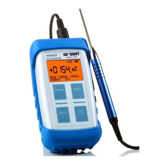
Gaussmeter HGM09s Operating Instructions Chapter 2 Brief Introduction 2.5 Display Display Display Display A typical example display is demonstrated below. USB Status Battery Status Unit Measuring Value Measuring Range Operating Mode Figure 1 Display 2.6 Stat Stat Stat Statu u u u s s s s Display... -
Page 10: Gaussmeter Function
Gaussmeter HGM09s Operating Instructions Chapter 3 Gaussmeter Function 3 3 3 3 Gaussmeter Gaussmeter Gaussmeter Gaussmeter Function Function Function Function 3.1 The Hall Effect The Hall Effect The Hall Effect The Hall Effect 3.1.1 3.1.1 Linear Properties of the Hall Probe 3.1.1... -
Page 11: Non-Linear Properties Of The Hall Probe
Gaussmeter HGM09s Operating Instructions Chapter 3 Gaussmeter Function ⋅ ⋅ It follows that: Hall ⋅ Carrier With Elementary charge of the electron (1.6022x10 Width of the path on which the electrons move Effective force of the Hall element Flux density in [Tesla] This represents the idealized Hall effect. -
Page 12: Probe Data 33
Gaussmeter HGM09s Operating Instructions Chapter 3 Gaussmeter Function 3.1.2.2 3.1.2.2 Reasons for the Field Dependenc 3.1.2.2 3.1.2.2 Reasons for the Field Dependenc Reasons for the Field Dependence e e e of the Sensitivity Reasons for the Field Dependenc of the Sensitivity... -
Page 13: Measurement Details
Gaussmeter HGM09s Operating Instructions Chapter 3 Gaussmeter Function 3.2 Measurement Measurement Measurement Measurement D D D De e e e tails tails tails tails The used Hall probes contain a very small active semiconductor area ranging at approx. 100µm. The local resolution of this measuring method is thus rather high. Also note that individual Hall probes measure one field component only. -
Page 14: Remanence And Hall Gaussmeter Measurement
Gaussmeter HGM09s Operating Instructions Chapter 3 Gaussmeter Function Figure 4 Field Strength Pattern of NdFeB Induction Disk The diagram in Figure 4 represents the measurement with a Hall probe which is moved in parallel to the surface of the magnet with a distance of 1mm distance to the measur- ing surface. -
Page 15: Accuracy Based On Positioning And Direction
Gaussmeter HGM09s Operating Instructions Chapter 3 Gaussmeter Function as well as are measured in the unit Tesla, the magnetic field measured on the outside is often mixed up with the remanence. Please note that a magnet a magnet a magnet without back iron only shows a value clearly... -
Page 16: External Static Magnetic Fields
Gaussmeter HGM09s Operating Instructions Chapter 3 Gaussmeter Function 3.2.4 3.2.4 External Static Magnetic Fields 3.2.4 3.2.4 External Static Magnetic Fields External Static Magnetic Fields External Static Magnetic Fields Particularly in sensitive measuring ranges, an external static magnetic field, as e.g. the Earth’s field, can already become clearly noticeable. -
Page 17: Control Elements And Connections
Gaussmeter HGM09s Operating Instructions Chapter 4 Control Elements and Connections 4 4 4 4 Control Elements and Connections Control Elements and Connections Control Elements and Connections Control Elements and Connections 4.1 Front Side Overview Front Side Overview Front Side Overview... -
Page 18: Power Supply
Gaussmeter HGM09s Operating Instructions Chapter 4 Control Elements and Connections 4.3 Power Power Power Power Supply Supply Supply Supply The gaussmeter can be operated with the included power supply. The power supply is connected via the USB port (type Mini-B) on the top of the device. The power supply is designed for a line voltage of 100 to 240V alternating current 50-60 hertz at a charging rate of max. -
Page 19: Charging The Batteries
Gaussmeter HGM09s Operating Instructions Chapter 4 Control Elements and Connections 4.4.1 4.4.1 Charging the Batteries Charging the Batteries 4.4.1 4.4.1 Charging the Batteries Charging the Batteries The battery is charged via the power supply during operation or when connected to a personal computer. -
Page 20: Probe Connection
Gaussmeter HGM09s Operating Instructions Chapter 4 Control Elements and Connections 4.5 Probe Connection Probe Connection Probe Connection Probe Connection The magnetic measuring probe is plugged into the probe port (DIN Mini-DIN- socket) on the top of the device. Note Only use measuring probes which are approved by the manufacturer to operate with this device. -
Page 21: Operation
Gaussmeter HGM09s Operating Instructions Chapter 5 Operation 5 5 5 5 Operation Operation Operation Operation 5.1 Keyboard Keyboard Keyboard Keyboard The required functions are selected and triggered via 4 buttons. The labeling of the button corresponds to the requested function, e.g. RANGE... -
Page 22: Display
Gaussmeter HGM09s Operating Instructions Chapter 5 Operation 5.2 Display Display Display Display A typical display example is shown below. USB Status Battery Status Unit Measuring Value Operating Mode Range Figure 8 Display 5.3 Stat Statu u u u s s s s Display... - Page 23 Gaussmeter HGM09s Operating Instructions Chapter 5 Operation The device is connected to the computer via a virtual inter- face. The device is connected to the computer as a keyboard simulation. In this mode, the gaussmeter acts like a key- Interface...
-
Page 24: Switching On/Off
Gaussmeter HGM09s Operating Instructions Chapter 5 Operation 5.4 Switching on/off Switching on/off Switching on/off Switching on/off The device is switched on and off with the right bottom IO IO button. In each case the button must be pressed for approx. 1 second. This avoids an accidental switching on and off. -
Page 25: Measuring Range
Gaussmeter HGM09s Operating Instructions Chapter 5 Operation 5.6 Measuring Range Measuring Range Measuring Range Measuring Range The gaussmeter has 4 measuring ranges. The range limit value is shown at the bottom left of the display. The range limit values depend on the ranges themselves and on the selected measuring unit. -
Page 26: Measuring Unit
Gaussmeter HGM09s Operating Instructions Chapter 5 Operation 5.7 Measuring Measuring Unit Unit Measuring Measuring Unit Unit You select the requested measuring unit by pressing the RANGE RANGE RANGE RANGE button. The function of the RANGE RANGE RANGE button depends on the setting of the setup... -
Page 27: Dc Field Measurements
Gaussmeter HGM09s Operating Instructions Chapter 5 Operation 5.8.1 5.8.1 5.8.1 5.8.1 DC Field Measurements DC Field Measurements DC Field Measurements DC Field Measurements When measuring DC fields, the gathered measuring values are integrated via a time interval of 100 milliseconds. Influences of AC magnetic fields are thereby sup- pressed. -
Page 28: Ac Field Measurements 28
Gaussmeter HGM09s Operating Instructions Chapter 5 Operation 5.8.2 5.8.2 AC Field Measurements 5.8.2 5.8.2 AC Field Measurements AC Field Measurements AC Field Measurements In the operating mode AC field measurement the effective value (RMS) calculated from determined AC field shares. DC field shares are automatically suppressed in this type of measure- ment. - Page 29 Gaussmeter HGM09s Operating Instructions Chapter 5 Operation Frequency Response Factor (Sinusoidal Field Pattern) Frequency Factor 2 kHz 1.00 5 kHz 0.98 7 kHz 0.95 10 kHz 0.90 Shape Factor (Sinusoidal Field Pattern) Factor Field Strength 700 mT 1.00 1000 mT 1.01...
-
Page 30: Normal Peak Value Recording
Gaussmeter HGM09s Operating Instructions Chapter 5 Operation 5.9 Peak Value Measurement Peak Value Measurement Peak Value Measurement Peak Value Measurement The device has 2 different operating modes for measuring peak values. They differ in speed, evaluation and resolution. 5.9.1 5.9.1 Normal Peak Value Recording 5.9.1... -
Page 31: Fast Peak Value Recording 31
Gaussmeter HGM09s Operating Instructions Chapter 5 Operation 5.9.2 5.9.2 5.9.2 5.9.2 Fast Peak Value Recording Fast Peak Value Recording Fast Peak Value Recording Fast Peak Value Recording The fast recording of the maximum values of DC fields is required for short magnetic impulses, as they are generated in e.g. - Page 32 Gaussmeter HGM09s Operating Instructions Chapter 5 Operation The error of the fast peak value measurement consists of the error of the DC field measurement and of a frequency factor that depends on the measuring range. Error DC Field Measurement (1σ) B ≤1.5 T...
-
Page 33: Probe Data
Gaussmeter HGM09s Operating Instructions Chapter 5 Operation 5.10 5.10 5.10 5.10 Probe Data Probe Data Probe Data Probe Data For a correct measurement the gaussmeter must always know the necessary probe data. The connected probes contain a parameter memory which stores the probe pa- rameters, the serial number and the labeling. -
Page 34: Setup Menu
Gaussmeter HGM09s Operating Instructions Chapter 6 Setup Menu 6 6 6 6 Setup Menu Setup Menu Setup Menu Setup Menu You can change the device setup via the setup menu and hence adapt the device to the measurement task in an optimal way. By holding the IO button after switching on, the setup menu appears on the display. -
Page 35: Settings
Gaussmeter HGM09s Operating Instructions Chapter 6 Setup Menu 6.1 Settings Settings Settings Settings The following setup possibilities can be adapted individually in order to be able to use the device for each application in an optimal way: 6.1.1 6.1.1 6.1.1 6.1.1 Operating Mode... -
Page 36: Operating Mode Of The Peak Value Recording
Gaussmeter HGM09s Operating Instructions Chapter 6 Setup Menu 6.1.3 Operating Mode of 6.1.3 Operating Mode of the the Peak Value Recording Peak Value Recording 6.1.3 6.1.3 Operating Mode of Operating Mode of Peak Value Recording Peak Value Recording Switched off... -
Page 37: Range Selection
Gaussmeter HGM09s Operating Instructions Chapter 6 Setup Menu 6.1.5 6.1.5 Range Selection Range Selection 6.1.5 6.1.5 Range Selection Range Selection MANU U U U ALLY ALLY ALLY ALLY Manual range selection RANGE RANGE RANGE RANGE via the button AUTO AUTO... -
Page 38: Charging The Batteries
Gaussmeter HGM09s Operating Instructions Chapter 6 Setup Menu 6.1.8 6.1.8 Charging the Batteries 6.1.8 6.1.8 Charging the Batteries Charging the Batteries Charging the Batteries The batteries are Charging is only possible when the charged via the power device is switched on. -
Page 39: Version Remarks
Gaussmeter HGM09s Operating Instructions Chapter 1 6.1.11 6.1.11 Version Remarks Version Remarks 6.1.11 6.1.11 Version Remarks Version Remarks After quitting the setup menu, two display pages emit some information regarding the device. If you want to look at the display longer, keep the IO IO button pressed. -
Page 40: Serial Interface
Gaussmeter HGM09s Operating Instructions Chapter 7 Serial Interface 7 7 7 7 Serial Interface Serial Interface Serial Interface Serial Interface 7.1 I I I I ntrodu ntrodu ntrodu ntroduction ction ction ction Via the installed serial interface all functions of the gaussmeter can be piloted by a controller (e.g. -
Page 41: Connecting The Gaussmeter To A Computer
Gaussmeter HGM09s Operating Instructions Chapter 7 Serial Interface 7.2 Connecting the Gaussmeter to a Computer Connecting the Gaussmeter to a Computer Connecting the Gaussmeter to a Computer Connecting the Gaussmeter to a Computer 7.2.1 7.2.1 7.2.1 7.2.1 Connector Plug Connector Plug... -
Page 42: Example Normal Measuring Mode In Excel
Gaussmeter HGM09s Operating Instructions Chapter 7 Serial Interface 7.3.1 Example Normal Measuring Mode in Excel 7.3.1 Example Normal Measuring Mode in Excel 7.3.1 7.3.1 Example Normal Measuring Mode in Excel Example Normal Measuring Mode in Excel The marked values were transmitted by the gaussmeter. -
Page 43: Operation Via Interface
Gaussmeter HGM09s Operating Instructions Chapter 7 Serial Interface 7.4 Operation via Interface Operation via Interface Operation via Interface Operation via Interface 7.4.1 7.4.1 Installation on the Computer Installation on the Computer 7.4.1 7.4.1 Installation on the Computer Installation on the Computer For the comprehensive operation on an external computer use the CDC device class (Communication Device Class) of the USB specification. - Page 44 Gaussmeter HGM09s Operating Instructions Chapter 7 Serial Interface 7.4.4.1 7.4.4.1 Command Structure 7.4.4.1 7.4.4.1 Command Structure Command Structure Command Structure The commands generally have a short and a long form. In the following descriptions, the short form is set in upper case. The attached long form is set in lower case. Only the characters of the short form are checked for syntactic correctness.
-
Page 45: Scpi Data Types
Gaussmeter HGM09s Operating Instructions Chapter 7 Serial Interface 7.4.4.6 7.4.4.6 7.4.4.6 7.4.4.6 Query Query Query Query Commands Commands Commands Commands The controller can send out commands at any time, however a SCPI device (here the gaussmeter) will only answer, if it has expressly been instructed to do so. Only query commands (commands that end with a question mark) prompt the device to send a response. - Page 46 Gaussmeter HGM09s Operating Instructions Chapter 7 Serial Interface 7.4.5.2 7.4.5.2 Discrete Parameters 7.4.5.2 7.4.5.2 Discrete Parameters Discrete Parameters Discrete Parameters Discrete parameters are used in order to program setups that have a limited amount of values. You have a long and a short form for command key words. Upper and lower case can be mixed.
- Page 47 Gaussmeter HGM09s Operating Instructions Chapter 7 Serial Interface 7.4.5.6 7.4.5.6 7.4.5.6 7.4.5.6 Output Data Output Data Output Data Output Data Format Format Format Format Output data have the format that is shown in the following chart. Output data always terminate with a <CR> character followed by an character.
-
Page 48: The Scpi Status Model
Gaussmeter HGM09s Operating Instructions Chapter 7 Serial Interface 7.4.6 The SCPI Status Model 7.4.6 The SCPI Status Model 7.4.6 7.4.6 The SCPI Status Model The SCPI Status Model The status system records different device conditions in several register groups. The individual messages are grouped in the several registers. - Page 49 Gaussmeter HGM09s Operating Instructions Chapter 7 Serial Interface 7.4.6.4 Overview Status Model 7.4.6.4 Overview Status Model 7.4.6.4 7.4.6.4 Overview Status Model Overview Status Model Figure 10 SCPI Status Model Page 49 / 75...
- Page 50 Gaussmeter HGM09s Operating Instructions Chapter 7 Serial Interface 7.4.6.5 Bit Definitions 7.4.6.5 Bit Definitions 7.4.6.5 7.4.6.5 Bit Definitions Bit Definitions Bit Definitions Sum Register Decimal Definition Value Measuring Event One or several bits are set in the measuring event regis- ter and activated in the release register.
-
Page 51: Summary Of Scpi Commands
Gaussmeter HGM09s Operating Instructions Chapter 7 Serial Interface 7.5 Summary of SCPI Commands Summary of SCPI Commands Summary of SCPI Commands Summary of SCPI Commands The following spellings are used in the SCPI command syntax: optional key words or parameters are indicated in square brackets [ ]. Parameters within a command character string are indicated in braces { }. -
Page 52: Probe Functions
Gaussmeter HGM09s Operating Instructions Chapter 7 Serial Interface :PEAK? Interrogate the current peak value mode. :PEAK:MODE {OFF|SLOW|FAST} Select the peak value mode. :PEAK:NULL Reset the current peak values. :PEAK:READ? Display the stored peak value. :PEAK:READ:MIN? Display the stored minimum peak value. -
Page 53: Explanation Of The Individual Scpi Commands
Gaussmeter HGM09s Operating Instructions Chapter 7 Serial Interface 7.6 Explanation Explanation Explanation Explanation of the Individual SCPI of the Individual SCPI of the Individual SCPI Commands of the Individual SCPI Commands Commands Commands 7.6.1 7.6.1 7.6.1 7.6.1 Control Commands Control Commands... - Page 54 Gaussmeter HGM09s Operating Instructions Chapter 7 Serial Interface 7.6.1.4 7.6.1.4 7.6.1.4 7.6.1.4 *IDN? *IDN? *IDN? *IDN? Description: Reads the gaussmeter identification character string. The gaussmeter displays the following identification text: Mode: Query Parameter: None value: Not relevant *RST Example: send *IDN?<LF>...
- Page 55 Gaussmeter HGM09s Operating Instructions Chapter 7 Serial Interface As the device interface is also reset, further commands on the inter- face might get lost. Mode: Command Parameter: None value: Not relevant *RST Example: send *RTS<LF> 7.6.1.8 7.6.1.8 7.6.1.8 7.6.1.8 *SRE[?]...
- Page 56 Gaussmeter HGM09s Operating Instructions Chapter 7 Serial Interface 7.6.1.11 7.6.1.11 7.6.1.11 7.6.1.11 :STAT:QUES:ENABle[?] :STAT:QUES:ENABle[?] :STAT:QUES:ENABle[?] :STAT:QUES:ENABle[?] Description: Reads out and sets the error byte release register. The gaussmeter displays a decimal value that corresponds to the sum of the binary place values of all set bits in this register.
-
Page 57: Main Commands
Gaussmeter HGM09s Operating Instructions Chapter 7 Serial Interface 7.6.1.14 7.6.1.14 7.6.1.14 7.6.1.14 :STAT:MEAS:EVENt? :STAT:MEAS:EVENt? :STAT:MEAS:EVENt? :STAT:MEAS:EVENt? Description: Reads out the event register. The gaussmeter displays a decimal value that corresponds to the sum of the binary place values of all set bits in this register. - Page 58 Gaussmeter HGM09s Operating Instructions Chapter 7 Serial Interface 7.6.2.3 7.6.2.3 7.6.2.3 7.6.2.3 :NULL :NULL :NULL :NULL Description: Null compensation of the measuring probe. This function should only be carried out in sufficiently field-free areas. Mode: Command Parameter: None value: Not relevant...
- Page 59 Gaussmeter HGM09s Operating Instructions Chapter 7 Serial Interface 7.6.2.6 7.6.2.6 :RANGe :RANGe? ? ? ? 7.6.2.6 7.6.2.6 :RANGe :RANGe Description: Interrogates the current measuring range. 0 = most sensitive range. Mode: Query Parameter: None value: Not relevant *RST Example: send :RANG?<LF>...
-
Page 60: Peak Value Function
Gaussmeter HGM09s Operating Instructions Chapter 7 Serial Interface 7.6.3 Peak Value Function 7.6.3 Peak Value Function 7.6.3 7.6.3 Peak Value Function Peak Value Function 7.6.3.1 7.6.3.1 :P :P :P :PEAK? EAK? 7.6.3.1 7.6.3.1 EAK? EAK? Description: Interrogates the current peak value mode. - Page 61 Gaussmeter HGM09s Operating Instructions Chapter 7 Serial Interface 7.6.3.4 7.6.3.4 7.6.3.4 7.6.3.4 :PEAK:READ? :PEAK:READ? :PEAK:READ? :PEAK:READ? Description: The stored peak value is displayed. For SlowPeak the absolute larger peak value with signs; for FastPeak the peak value; for normal measurement 0 is emitted.
-
Page 62: Probe Functions
Gaussmeter HGM09s Operating Instructions Chapter 7 Serial Interface 7.6.4 Probe Functions 7.6.4 Probe Functions 7.6.4 7.6.4 Probe Functions Probe Functions 7.6.4.1 7.6.4.1 :PROB:NAME? :PROB:NAME? 7.6.4.1 7.6.4.1 :PROB:NAME? :PROB:NAME? Description: Interrogates the probe name. Mode: Query Parameter: None value: Not relevant... -
Page 63: Parameters
Gaussmeter HGM09s Operating Instructions Chapter 7 Serial Interface 7.6.5 7.6.5 Parameters Parameters 7.6.5 7.6.5 Parameters Parameters 7.6.5.1 7.6.5.1 :PAR:USB[?] :PAR:USB[?] 7.6.5.1 7.6.5.1 :PAR:USB[?] :PAR:USB[?] Description: Selects the USB interface operating mode. A change of this parame- ter has an effect only after the next switching-on of the device. The changes must be stored by the command :PAR:SAVE, if necessary. - Page 64 Gaussmeter HGM09s Operating Instructions Chapter 7 Serial Interface 7.6.5.3 7.6.5.3 7.6.5.3 7.6.5.3 :PAR:PEAK[?] :PAR:PEAK[?] :PAR:PEAK[?] :PAR:PEAK[?] Description: Selects the peak value acquisition mode. The changes must be stored by the command :PAR:SAVE, if necessary. Mode: Command and query Parameter: {OFF | SLOW | FAST}...
- Page 65 Gaussmeter HGM09s Operating Instructions Chapter 7 Serial Interface 7.6.5.5 7.6.5.5 7.6.5.5 7.6.5.5 :PAR:RANGe[?] :PAR:RANGe[?] :PAR:RANGe[?] :PAR:RANGe[?] Description: Switches on/off the automatic range selection. The changes must be stored by the command :PAR:SAVE, if necessary. Mode: Command and query Parameter: {MANU | AUTO}...
- Page 66 Gaussmeter HGM09s Operating Instructions Chapter 7 Serial Interface MANU Switch off the automatic turn-off 2MIN Automatic turn-off after 2 minutes 5MIN Automatic turn-off after 5 minutes value: Not relevant *RST Example: send :PAR:POFF MANU<LF> send :PAR:POFF?<LF> receive MANU<CR><LF> 7.6.5.8 7.6.5.8 7.6.5.8...
-
Page 67: Device Functions
Gaussmeter HGM09s Operating Instructions Chapter 7 Serial Interface Example: send :PAR:LIGH 75<LF> send :PAR:LIGH?<LF> receive 100<CR><LF> 7.6.5.10 7.6.5.10 7.6.5.10 7.6.5.10 :PAR:CONTrast[?] :PAR:CONTrast[?] :PAR:CONTrast[?] :PAR:CONTrast[?] Description: Sets the display contrast. The changes must be stored by the com- mand :PAR:SAVE, if necessary. The value corresponds to 5% steps. - Page 68 Gaussmeter HGM09s Operating Instructions Chapter 7 Serial Interface 7.6.6.2 7.6.6.2 7.6.6.2 7.6.6.2 :SN:SW? :SN:SW? :SN:SW? :SN:SW? Description: Emits the software version. Mode: Query Parameter: None value: Not relevant *RST Example: send :SN:SW?<LF> receive 180310<CR><LF> 7.6.6.3 7.6.6.3 :SN:HW :SN:HW 7.6.6.3 7.6.6.3...
-
Page 69: Unit Conversion Table
Gaussmeter HGM09s Operating Instructions Chapter 8 Unit Conversion Table 8 8 8 8 Unit Unit Unit Conversion Table Unit Conversion Table Conversion Table Conversion Table This table shows the relationship between the displayed measuring values. Size Unit Display Conversion Mag. flux density B Tesla ⋅... -
Page 70: Technical Data
Gaussmeter HGM09s Operating Instructions Chapter 9 Technical Data 9 9 9 9 Technical Data Technical Data Technical Data Technical Data General General General General Power Supply Power supply unit 100..240 VAC, 50/60Hz, 0.3 A USB interface Battery 2 x AA 1.2 V NiMH (rechargeable) Power Consumption approx. - Page 71 Gaussmeter HGM09s Operating Instructions Chapter 9 Technical Data Units Tesla Gauss Oersted Ampere/meter 4.5 T 45 kG 45 kOe 3800 kA/m Measuring Ranges (1 mT) (10 G) (10 Oe) (1 kA/m) (Resolution) 10 kG 10 kOe 1000 kA/m DC Field Measurement (100 µT)
-
Page 72: 10 Declaration Of Conformity
Date / M. Kopka Dipl.Ing. CEO For further information, please contact your local Goudsmit Magnetic Systems sales office, agent or distributor, or Goudsmit Magnetic Systems, Petunialaan 19, 5582HA, Waalre, Netherlands. www.goudsmit-magnetics.nl Für weitere Informationen kontaktieren Sie bitte Ihr örtliches Goudsmit Magnetic Systems Vertriebsbüro, Handelsvertreter oder Händler oder direkt Goudsmit Magnetic Systems, Petunialaan 19, 5582HA, Waalre, Netherlands. -
Page 73: 11 Warranty And Copyright
The above-mentioned measures are the only and exclusive despite all efforts, we would appreciate any given hint. We measures on the side of the buyer. Goudsmit Magnetic Sys- will be striving to fix any mistake as fast as possible. tems is not liable for direct, indirect, particular damages or... -
Page 74: Index
Gaussmeter HGM09s Operating Instructions Chapter 12 Index 12 I I I I ndex ndex ndex ndex Accuracy........15 * * * * L L L L B B B B *CLS........... 53 Linear Properties ......10 *ESE .......... 53 Batteries ........18 *ESR .......... - Page 75 Gaussmeter HGM09s Operating Instructions Chapter 12 Index Switching off ....... 37 U U U U V V V V Switching on/off ......24 Unit ..........69 Version Remarks......39 System Commands ....45 USB ..........41 USB Interface ......20...
Need help?
Do you have a question about the HGM09S and is the answer not in the manual?
Questions and answers
I **** looking for a specific nominal gauss readings at a specific distance and depth on a magnet. Are there holding devices for the HGM09 model that can do this or do we need to make our own?