Table of Contents
Advertisement
Quick Links
UFo comPacT 150 w dmX + Universal illUminaTor
Please read This User GUide beFore insTallinG
User GUide
:
b 1
revision
models covered
UFo 150 cdmX+G-dcT / UFo 150 cdmX+G-dcT
UFo 150 cdmX+G-dc / UFo 150 cdmX+G-cT
UFo 150 cdmX+G-c / UFo 150 cdmX+G-d
UFo 150 cdmX+P-dcT / UFo 150 cdmX+P-dc
UFo 150 cdmX+P-cT / UFo 150 cdmX+P-c
UFo 150 cdmX+P-d / UFo 70 cdmX+G-dcT
UFo 70 cdmX+G-dc / UFo 70 cdmX+G-cT
UFo 70 cdmX+G-c / UFo 70 cdmX+G-d
UFo 70 cdmX+P-dcT / UFo 70 cdmX+P-dc
UFo 70 cdmX+P-cT / UFo 70 cdmX+P-c
UFo 70 cdmX+P-d
or oPeraTinG This illUminaTor
UFo liGhTinG
Fiber oPTic & led liGhTinG sysTems
:
,
.
connecTinG
Advertisement
Table of Contents

Subscribe to Our Youtube Channel
Related Manuals for UFO 150 CDMX+G-DCT

Summary of Contents for UFO 150 CDMX+G-DCT
- Page 1 UFo liGhTinG Fiber oPTic & led liGhTinG sysTems UFo comPacT 150 w dmX + Universal illUminaTor models covered UFo 150 cdmX+G-dcT / UFo 150 cdmX+G-dcT UFo 150 cdmX+G-dc / UFo 150 cdmX+G-cT UFo 150 cdmX+G-c / UFo 150 cdmX+G-d UFo 150 cdmX+P-dcT / UFo 150 cdmX+P-dc...
- Page 2 7. Do not operate product with missing or damaged guard, lamp containment barrier, lens or fiber optic harness. 8. Contact UFO for replacement lamp guard, lamp containment barrier, lens or fiber optic harness 9. Lamp types are matched to the ballast and different wattages/types cannot be used.
- Page 3 This is to allow air to circulate and prevent overheating. The location must have free ventilation and must not have a ambient temperature higher than that specified for the luminaire. MOUNTING: This is a fixed luminaire. See separate mounting instructions for fixing to surface. WARNING: Never look directly into the luminaire illuminator. UFo liGhTinG...
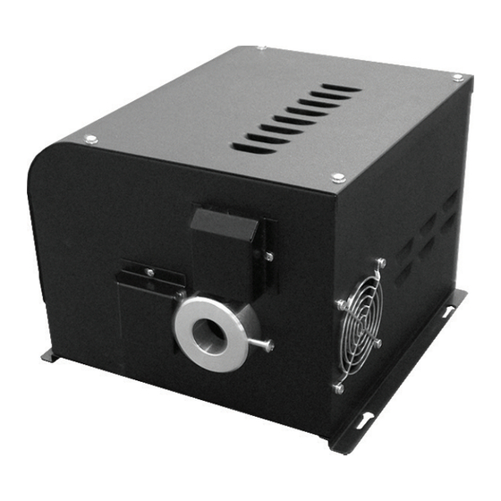
- Page 4 illUminaTor layoUT Item Description dmX connection sockets led display and control buttons Power led mains power input lamp holder cooling fan motor covers Fiber port 4 x access screws 4 x mounting holes 150 w Universal dmX + User GUide...
-
Page 5: Installation
If the unit is being mounted at a higher than the ground level, block access below the work area before installing. Verify that any screws or bolts can safely bear the weight of the illuminator. UFo liGhTinG... - Page 6 insTallaTion Verify that the supporting structure can safely bear the weight of all installed units, cables and any other equipment. For horizontal mounting, it is recommended that the illuminator is secured to a solid surface using 4 x M4 or M5 screws or bolts and the keyhole slots. This is particularly important if the illuminator location is not at ground floor level.
-
Page 7: Operation
The lamp will take 3-4 minutes to reach full brightness. This is normal for this type of il- luminator. During the power up sequence the software version number and the model version is displayed momentarily as detailed below: If no light is produced, please consult the TROUBLESHOOTING section in this manual. UFo liGhTinG... -
Page 8: Rear Panel Controls
oPeraTion REAR PANEL CONTROLS NOTE 1. The left hand display module shows a rotating ‘X’ when DMX data is present. 2. The microphone (under the display) for sound to light applications is a fully functional device, but is not implemented in the software. This application is a special feature on request. 150 w Universal dmX + User GUide... -
Page 9: Rear Panel Connectors
2. DMX IN - standard 3-pin DMX input connector 3. AC IN - standard fused IEC power connector 4. DATA OUT - RJ45 connection to UFO RIU (remote indicator unit) The DMX wiring connections are detailed below: Like all data networks the DMX cable should be terminated on the DMX out of the last illumina- tor using a terminator plug. -
Page 10: Standalone Mode
oPeraTion The dmX+ illuminator has two modes of operation - standalone and dmX. STANDALONE MODE In standalone mode, the Compact DMX+ can be used in two ways - either as a single independent illuminator or in master/slave configuration with several illuminators connected together using DMX cables. - Page 11 PROGRAMMING THE DMX UFo liGhTinG...
- Page 12 oPeraTion PROGRAMMING THE DMX 150 w Universal dmX + User GUide...
-
Page 13: Dmx Channel Information
3. Colors 1-9 shown represent standard colors 4. Channel 5 adjusts the “snap” speed between colors Unit numbers: (1) All model versions / (2) models 3DCT, 2DC, 1D / (3) models 3DCT, 2DC, 2CT, 1C / (4) models 3DCT, 2CT UFo liGhTinG... - Page 14 sTandalone masTer ProGrammable FUncTions Prog Function Unit Prog Function Unit Pa01 color 9, no twinkle Pc01 snap color change 0-9, no twinkle Pa02 color 8, no twinkle Pc02 snap color change 1-9, no twinkle Pa03 color 7, no twinkle Pc03 snap color change 2-9, no twinkle Pa04 color 6, no twinkle...
-
Page 15: Cleaning The Unit
Glass filter to be cleaned with soap and water then dried. MAINTENANCE LOG Please note that a record of all maintenance MUST be kept in the table below, indicating what maintenance was undertaken and when. This must be dated for warranty purposes.. Date Maintenance Undertaken UFo liGhTinG... -
Page 16: Lamp Replacement
mainTenenace LAMP REPLACEMENT A lamp replacement every 12 months is recommended for metal halide illuminators. 1) Unplug unit from electrical supply and allow to cool. 2) On the rear of the unit, unscrew the two knurled securing nuts (A) which hold the lamp holder in position. -
Page 17: Fuse Replacement
There is also a spare fuse located in this drawer. 3) Open the fuse drawer. 4) Withdraw fuse from its holder 5) Replace with identically specified fuse - see specification table in this manual. 6) Close the fuse drawer and power up the illuminator. UFo liGhTinG... -
Page 18: Troubleshooting
UFo for assistance Probable Cause Remedy Fan has failed or is failing replace fan Unit overheating - too hot an environment... - Page 19 Glue magnet back on wheel in correct place dimmer wheel magnet fallen off or not being check magnet sensor alignment sensed by sensor Pcb, due to too wide a gap or sensor cable plug dislodged check sensor cable plugged in to main Pcb correctly UFo liGhTinG...
- Page 20 Unit does not reset correctly contact UFo for assistance adjustment lamp too hot to strike allow lamp to cool no light output...
-
Page 21: Technical Specifications
Protection rating iP20 material / color sheet steel / black powder coated size / weight 282mm (11.1”) (l) x 300mm (11.8”) (w) x 210mm (8.27”) (h) / 7.66kg * lamp life as stated by manufacturer in optimum conditions UFo liGhTinG... - Page 22 noTes 150 w Universal dmX + User GUide...
- Page 23 UFo liGhTinG...
- Page 24 Europe • desiGn sPeciFy bUild insTall UFO Licht GmBH Universal Fiber Optic lighting LLC Universal Fibre Optics Ltd Das Runde Haue GBR 6119A Clark Center Avenue Home Place Gewerbering Ost 5b Sarasota, FL34238 Coldstream, TD12 4DT 93155 Hemau, Deutschland...
Need help?
Do you have a question about the 150 CDMX+G-DCT and is the answer not in the manual?
Questions and answers