Table of Contents
Advertisement
Quick Links
Advertisement
Table of Contents

Related Manuals for Spectrum Technologies Field Scout TDR 350


Summary of Contents for Spectrum Technologies Field Scout TDR 350
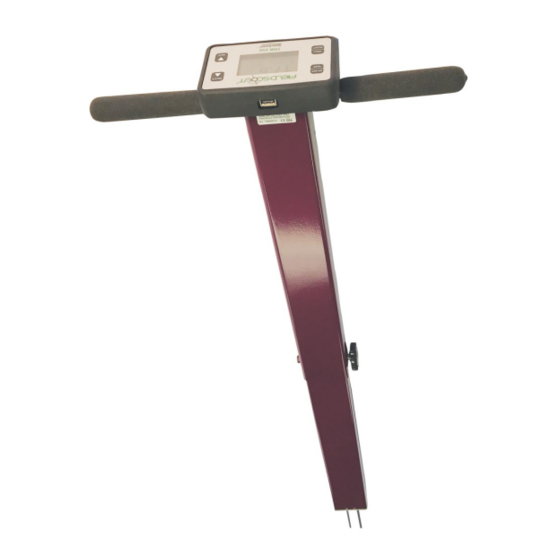
- Page 1 TDR 350 Soil Moisture Meter PRODUCT MANUAL Item # 6435...
-
Page 2: Table Of Contents
CONTENTS Shaft Dimensions Specifications Batteries Button Functions Display Screens Meter Calibration Updating Firmware Electrical Conductivity Meter Operation Replacing or Re-attaching the Probe Block Replacing the Display Field Scout Mobile App/SpecConnect Pairing TDR350 with FieldScout Mobile App Data Logs VWC Measurements GPS Status Optional Accessories Appendix 1: Checking VWC Readings... - Page 3 General overview Thank you for purchasing the Field Scout TDR 350 soil moisture, electrical conductivity and soil surface temperature meter. This manual describes the meter's general features and operation. Soil moisture is a critical, and potentially highly varia- ble, component of the soil environment. Time domain reflectometry is a proven technology for quickly and accurately determining volumetric water content (VWC) in soil.
-
Page 4: Shaft Dimensions
Shaft dimensions The following are the dimensions of a fully extended shaft. It is possible to reduce the length of the meter to 23” (58.5 cm) by adjusting the lower half of the shaft. 14" 5" 19.5" 38" 2.4"... -
Page 5: Specifications
Specifications Measurement Percent volumetric water content (VWC) Units Period (raw sensor reading) Resolution VWC: 0.1% VWC units EC: 0.01 mS/cm Temperature: 0.2 ˚F (0.1 ˚C) Accuracy VWC: ±3.0% volumetric water content with electrical conductivity < 2 mS/cm EC: ± 0.1 mS/cm Temperature: ±... -
Page 6: Batteries
Batteries Changing the batteries The TDR 350 requires 4 AA batteries. The battery holder is on the underside of the display unit. The sensor is at- tached to the display via a cable that is plugged into a socket between the battery holders. The cable can be pulled out of and pushed back into the shaft through a grommet at the top of the shaft. - Page 7 Battery life The battery level is checked every time the display unit is turned on. If the battery level is low, or if a battery is inserted incorrectly, this low battery im- age shows on the full screen for about 10 seconds and then the display will automatically turn off.
-
Page 8: Button Functions
Button Functions Basic Button Operations ON/OFF or BACK button Press this button briefly to turn on the display. The meter will then display the Data screen (p. 11). To turn the meter off, press and hold this button for about 2 seconds. When in the Settings Menu screen (p. - Page 9 DELETE or UP button When on the Data screen (p. 11), press this button to delete the last measured data point from the computed Average and decrement the Count. When on the Settings Menu screen (p. 12), press this button to scroll up to the previous menu item. READ or DOWN button When on the Data screen, press and release this button to take a sensor...
-
Page 10: Display Screens
Display Screens The TDR 350 has 3 main display screens; - Startup Information screen - Data screen - Settings Menu screen Startup Information screen The Startup Information screen is displayed for about 2 seconds after the display is turned on. If desired, the startup screen can be kept on for a longer duration. - Page 11 Data screen Readings from the sensor are displayed on the Data screen. The battery level in- dicator appears in the upper right corner. The run- ning average and number of readings included in that average are shown in the lower right corner. Pressing and holding the READ button will clear the average and re-set the counter to 0.
- Page 12 Settings Menu screen The contents of the Settings Menu are shown on the following figure. Use the arrow buttons to scroll to the desired option. The options are described below. For most options, pressing the Select button simply tog- gles you through the different choices for that option. Some options require an additional step or steps.
- Page 13 Temp Source: Choose Soil Sensor or IR Sensor. Temp Units: Choose Fahrenheit or Celsius. Moisture Type: Choose volumetric water content (VWC%), raw sensor reading (Period), or TDR 300 mode. The latter will report a VWC that matches the out- put of the TDR 300 meter (no EC optimization). EC Units: Choose simple EC value (mS/cm) or the Sa- linity Index (see p.
-
Page 14: Meter Calibration
Meter Calibration The meter has internal calibrations for standard, sand, and high-clay soil types. It also has the op- tion of outputting a value that matches its prede- cessor, the TDR 300. These calibrations will work for a large number of soils. However, each meter will have a small difference in how it responds to identical soil conditions. -
Page 15: Updating Firmware
The meter will then show that the calibration is complete for that specific rod length. If more than one rod size is being used, a calibration operation must be done for each one. Note: This procedure is different than a soil- specific calibration (Appendix 2, p. -
Page 16: Electrical Conductivity
Electrical Conductivity Electrical Conductivity Knowledge of the salinity level of your soil is an im- portant component of irrigation and nutrient management. The source of the salts in the soil ranges from the original parent material to additions from natural sources and man- agement activity. - Page 17 Salinity Index The TDR 350 measures the bulk EC of soil that may or may not be saturated. There are two competing mecha- nisms at place. As the soil dries, the remaining solution in the pore space becomes more concentrated which increas- es its EC.
-
Page 18: Meter Operation
Meter Operation Figure 1. Shaft, fastening bolt, and rods Setting up the meter The telescoping shaft (fig. 1) can be used in an extended or retracted position. To adjust the length, remove the fas- tening bolt and push or pull the shaft into its new posi- tion. - Page 19 To geo-reference data, enable the GPS capability. If you are using the FieldScout Mobile app (p. 22), Bluetooth functionality must be enabled. When Bluetooth is activat- ed, it will always be on while meter is powered up. If GPS is disabled, the app will use the phone's GPS in- stead.
- Page 20 other material that can cause the rods to deflect or bend. If the ground is especially hard or compact, you can use a Pilot Hole maker (item 6430PH) to make 3” holes to aid in starting the insertion of the probe rods. Press the READ button to initiate the measurement se- quence.
-
Page 21: Replacing Or Re-Attaching The Probe Block
Replacing or Re-attaching the Probe Block Figure 1. Sensor cable Figure 2. Sensor block/ connection to board. shaft interface The TDR 350 sensor block is a user-replaceable com- ponent (item 6435S). Remove the rods before separat- ing the old sensor. 1. -
Page 22: Replacing The Display
Replacing the Display Remove the rods before separating the old display from the probe block. The shaft should be collapsed before beginning the procedure. 1. Turn the TDR 350 upside down and remove the 4 screws. Open the bottom and separate the display module from the base plate (fig. -
Page 23: Field Scout Mobile App/Specconnect
Field Scout Mobile App/ SpecConnect In addition to transferring data to a flash drive, the FieldScout Mobile App can be used to send data directly to the SpecConnect web utility. Data can be viewed on a Smartphone in two formats. In grid mode, the site is divided into a customizable 2- dimensional grid of 3 to 5 rows and 3 to 5 col- umns. - Page 24 The data from the Pro version of the app is sent instantaneously to SpecConnect. Data can be viewed in map form (fig. 3), exported to an Excel spreadsheet, or viewed as a Trend Report (fig. 4). More details are available in the user's guide for the app.
-
Page 25: Pairing Tdr350 With Fieldscout Mobile App
Pairing TDR350 With FieldScout Mobile App The internal Bluetooth radio must be paired with the smartphone running FieldScout Mobile. The radio is activated when the meter is powered up. For some smartphone operating systems, it may be necessary to manually enable Location Services. 1. - Page 26 b. For Freeform mode, the app will immediately transition to the Take Reading screen (Fig. 3). 6. Tap the Connect FieldScout Device via Bluetooth button. If the Bluetooth feature has not been activated, you will be prompt- ed to do so. 7.
-
Page 27: Data Logs
Data Logs Figure 1: Sample TDR 350 data file Downloading Data Data stored in the meter's internal memory can be transferred to your PC with a USB flash drive. Connect the flash drive to the USB port on the front of the meter. Press the Menu/Select button (p. - Page 28 meter. These files can be opened with text-editing software or spreadsheet software (fig. 1). The data is separated into 11 fields. Column Description Date and time 2 - 6 Sensor readings (VWC, Period, EC, Soil Temperature, IR Temperature) 7 - 8 GPS coordinates (longitude, latitude) Number of satellites visible during reading Satellite fix status...
-
Page 29: Vwc Measurements
VWC Measurements Volumetric Water Content (VWC) The soil can be thought of as being composed of soil, water and air. The volumetric water content (VWC) is the ratio of the volume of water in a given volume of soil to the total soil volume. -
Page 30: Gps Status
Electronics in the TDR 350 generate and sense the return of a high energy signal that travels down and back, through the soil, along the waveguide composed of the two replaceable, stainless steel rods. The sampling volume is an elliptical cylinder that extends approximately 3 cm out from the rods. -
Page 31: Optional Accessories
Optional Accessories There are two optional items that can be used to expand the capabilities of the TDR350. They are described briefly below. See the website for the product's specific user information and installation instructions. Infrared Temperature Sensor (item 6435TS) The Infrared Temperature Sensor is an alternate to the sur- face temperature sensor. -
Page 32: Appendix 1: Checking Vwc Readings
Appendix 1 Checking VWC Readings There are two tests that can be performed to check if the meter is operat- ing properly. Test 1 (No rods): Disconnect the rods from the probe block. Select the Period option for Moisture Type (p. 13). With no rods connected, the meter should read 1930 ±... -
Page 33: Appendix 2 Soil-Specific Calibration
Appendix 2 Soil-Specific Calibration For maximum accuracy, you may choose to perform a soil-specific calibration rather than use either of the internal (Standard, High Clay, or Sand) soil calibrations coded into the TDR 350’s firmware. In these cases, an independent soil moisture content measurement is required. - Page 34 VWC = 100*(M )/( Where: mass (g) of wet and dry soil respectively wet, total soil volume (ml) density of water (1g/ml) An alternate, but equivalent, calculation can be obtained from the gravimetric water content and soil bulk density. ...
-
Page 35: Appendix 3: Faq
Overlay Service (EGNOS) is used in Europe. 4. How do I get access to SpecConnect? SpecConnect is a subscription-based web utility. Contact Spectrum Technologies or your distributor for details. 5. I cannot save data or load firmware with my USB flash drive. - Page 36 Spectrum is not responsible for any package that is returned without a valid RMA number or for the loss of the package by any shipping company. DECLARATION OF CONFORMITY Spectrum Technologies, Inc. 3600 Thayer Ct. Aurora, IL 60504 USA Model Numbers:...
Need help?
Do you have a question about the Field Scout TDR 350 and is the answer not in the manual?
Questions and answers