
Related Manuals for DIGITALas MDVR-4F1AHD

Summary of Contents for DIGITALas MDVR-4F1AHD
- Page 1 1080P AHD HDD MDVR MDVR-4F1AHD professional car video recorder USER MANUAL FTH-DVR-B7 Further Technology(Dongguan) Co., Limited...
-
Page 2: Table Of Contents
Contents 1. System Introduction........................3 2. Specification............................4 3. Considerations..........................7 4. Interface Description........................9 4.1 Front Panel Description......................9 4.1.1 Indicator Function Description.................. 9 4.1.2 Other definitions......................9 4.2 Rear View..........................10 4.2.1 The rear panel definition..................10 4.2.2 Power cord special instructions................10 4.2.3 Audio/video input/output Description..............11 4.2.4 GPS、3G/4G Antenna、Wi-Fi Antenna.............. -
Page 3: System Introduction
System Introduction Product features H.264 Compression Mode, Support 4CH real-time 720P AHD/1080P AHD High Definition camera input; Exclusive pre-allocate DVR Special File System Technology,Solving repeatedly wipe cause file fragmentation, solving SD card file system collapse, data loss and cannot find SD card and file garbled, ensure the integrity of the data. -
Page 4: Specification
Support GPS/BD,G-sensor Modules Extension. 3channels RS232 +1channel RS485. Superior network function, support mobile SMS to configure parameters and obtain device information. Support Video&Audio monitoring,2-way Intercom, PTZ control, manually Alarm,Over-speed,Geo Fence etc through remote control platform. 8CH alarm inputs (Doors, lights, steering, braking, reversing and all types can be ... - Page 5 PAL: 100f/s , CCIR625 line,50field; NTSC: 120f/s, CCIR525 line,60field; CIF: 256Kbps ~ 1.5Mbps, multi levels video quality optional; Video Standard HD1: 600Kbps ~ 2.5Mbps, multi levels video quality optional; D1: 800Kbps ~ 3Mbps, multi levels video quality optional; 720P : 1Mbps~4Mbps, multi levels video quality optional; 1080P: multi levels video quality optional;...
- Page 6 Voltage Output +12V@2.5A,+5V@2.5A Power-off UPS Technology,All video information can be saved automatically when the Protection power is cut off, and make sure that all the files can not be damaged. Power Normal Working <10W Consumption Working Temperature -20℃ to +70℃ Environme Humidity 20% to 80%...
-
Page 7: Considerations
3. Considerations In order to ensure the safely use of FTH-DVR-B7 Mobile DVR device, please carefully read and observe the following precautions: 3.1 when installing and operating the equipment, comply with all the norms of electronic products, as well as vehicles and other connected equipment. 3.2 Power and Ground: The Projector range of DC input power directly 6V to 36V, often powered from the vehicle battery (or distribution box) To take power, please be careful not to... - Page 8 other vehicle components restricted areas. installation of equipment components, cameras, accessories, and when the wire, launch vehicle may cause damage to the equipment, make sure the vehicle is stationary during installation, to prevent the unit from dropping. xii. screws fastening the device must be strong, can not loose, to ensure the stability of the device.
-
Page 9: Interface Description
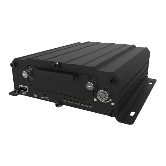
Interface Description Front Panel Description 4.1.1 Indicator Function Description [PWR] Power Status Indicator: LED lit ─ charging system [GPS] GPS status light: LED flashes ─GPS loaded successfully [HOT] heating status lights: Reserve [HDD] HDD LED: LED lights ─ hard disk loading. LED flashes ─ a description of this disc is recording or reading and writing data [SD] SD indicator: LED lights ─SD Calgary uploaded successfully. -
Page 10: Rear View
Rear View 4.2.1 The rear panel definition [DC8-36V] Power Interface: left upper and lower 2PIN is DC +, down the middle 2PIN ● is DC-, is on the right side 1PIN ACC, under the right of 1PIN is 12V-OUT. [NET] network interface. ●... -
Page 11: Audio/Video Input/Output Description
4.2.2.1 Power cable pin definitions Color Line Name Description Power-Positive Black Yellow 12V-OUT 12V output 4.2.2.2 Wiring: red and black wire are connected directly to the car battery. Red wire to positive, black to negative. Yellow line contacts FireWire, ignition switch mode is set to mode. - Page 12 Female connector definition: Video Video Audio Function 12V output Audio input1 input 1 input2 input 2 Color White Black Blue Yellow Green Male signal connector definition: Function Audio input Video input 12V output Color Green/White Yellow/Blue Black Audio/Video output 【AV-OUT】 +12V (red) GND (black) Audio (green)
-
Page 13: Gps、3G/4G Antenna、Wi-Fi Antenna
4.2.4 GPS、3G/4G Antenna、Wi-Fi Antenna GPS Antenna 3G/4G Antenna Wi-Fi Antenna Host installation Instruction 4.3.1 Wiring diagram GPS Antenna antenna 3G/4G antenna camera2 camera1 WIFI speaker/232 camera4 camera3 Line Power LAN/RJ4 Alarm lines people counter/oil sensor/Tyre sensor etc -----------------------------------------------------------------------------------------------------------------------------------... - Page 14 ALM/232/485/CAN connection lines -----------------------------------------------------------------------------------------------------------------------------------...
-
Page 15: Hdd Installation
ALM/232/MIC/SPK extension lines Power Cables Line Item Remark color Power positive Black yellow ACC line 12V-OUT 12V output 4.3.2 HDD Installation Hard disk installation steps: 1、 Open the hard disk lock and un-screw the 2 fixing screws, pull out the hard disk box,, as shown in FIG. - Page 16 HDD box Lock Box Fixing screw2 Box Fixing screw1 2、Unscrew 4pcs screw on HDD box,as show below HDD box screw HDD box screw HDD box screw HDD box screw 3.Install shock absorption foam on both sides of the hdd, connect the HDD with SATA lines,fix the HDD into the dedicated ditch, as shown below SATA line HDD installation diagram...
-
Page 17: Sd Card, Sim Card Installation
HDD box screw HDD box screw HDD box screw HDD box screw Note: Be sure to lock the hard disk installed hard disk lock, otherwise the host may not start. 4.3.3 SD card, SIM card installation With a key to open the box to pull out the hard disk box, , then you can see SD card port, as shown below. - Page 18 Login Menu Menu Diagram -----------------------------------------------------------------------------------------------------------------------------------...
-
Page 19: Remote Control
Remote Control 5.2.1 System Key Turn on/ off key 【 】: Info. Key (retain) 【Info】: Lock. Press this key to lock remote input after exiting menu. 【 】: Switch 1~4 screens. Number keys 1~4 can do this too. 【 】: -----------------------------------------------------------------------------------------------------------------------------------... -
Page 20: Menu-Key Function Description
:Delete key. 【Del】 【 】 Number/Letter Input key, you can input the number value to select a single channel preview. 5.2.2 Menu-key Function Description MENU Start/Login/Exit menu 【 】 EXIT Back to the previous menu 【 】 Last program 【 】 Next program 【... -
Page 21: Main Menu
Press 【OK】 to enter the edit mode, input password , press 【EXIT】 to exit the edit, Press【OK】 to enter the Main Menu. Original Password: 111111 5.3.2 Main Menu Exit Menu 【EXIT】 -----------------------------------------------------------------------------------------------------------------------------------... - Page 22 5.3.2.1 Inquiry Function: Query the recording information. Operation: In the main menu, press the remote control 【 】 【 】 【 】 【 】 key, select and operate. [Image Search] Function: Search preferred video information. Operation: In query interface, press remote control key【 】 【 】 【 】 【 】 ,select [RECORD],press [ENTER] and go to video search Menu as below Select the right time and search the video -----------------------------------------------------------------------------------------------------------------------------------...
- Page 23 [Log Search]: query log information. Operation: In query interface, press remote control key 【 】 【 】 【 】 【 】 ,select [Log Search],press [ENTER] and go to video search Menu as below [Image Query]: query image information. Operation: In query interface, press remote control key 【 】 【 】 【 】 【 】 ,select [Image Search],press [ENTER] and go to log search Menu as below -----------------------------------------------------------------------------------------------------------------------------------...
- Page 24 5.3.2.2 System Management Function: Set each property of the Device. Operation:In query interface, press remote control key 【 】 【 】 【 】 【 】,select [System Management],press [ENTER] and go to video search Menu as below In the System settings interface, press on the remote control 【 】【 】【 】 【...
- Page 25 [User Management] Function: Manage the user information. Operation:In user manage interface, press remote control key 【 】【 】【 】 【 】,select [User Management],press [ENTER] and go to the Menu as below [System time] Function: set up the system time. Operation:In system time interface, press remote control key 【 】【 】【 】 【...
- Page 26 [Power manage] Function: set up the DVR power on/off parameters. Operation: In power manage interface, press remote control key 【 】 【 】 【 】 【 】,select [power manage],press [ENTER] and go to the Menu as below [Parameter Set] Function: set up/Import/Export/Recover the DVR Parameters.. Operation:In system set up interface, press remote control key 【...
- Page 27 [Format] Function: Format DVR storage medias(USB1--HDD).. Operation:In system set up interface, press remote control key 【 】 【 】 【 】 【 】,select [format],press [ENTER] and go to the Menu as below 5.3.2.3 Record Setting In Main Menu interface, press remote control key 【 】【 】【 】【 】,select [video set],press [ENTER] and go to the Menu as below -----------------------------------------------------------------------------------------------------------------------------------...
- Page 28 [Basic set] Function: Set up video record and display basic parameters Operation:In the video set up interface, press remote control key 【 】【 】 【 】【 】,select [Basic set],press [ENTER] and go to the Menu as below [Main video stream] Function: Modify the main video stream parameters Operation:In the video set up interface, press remote control key 【...
- Page 29 [Sub-stream] Function: Modify video sub-stream parameters Operation:In the video set up interface, press remote control key 【 】【 】 【 】【 】,select [Sub-stream],press [ENTER] and go to the Menu as below [Timer recording] Function: Set up Timer recording. Operation:In the video set up interface, press remote control key 【 】【 】 【...
- Page 30 [Storage Set] Function: Set up Storage items. Operation:In the video set up interface, press remote control key 【 】【 】 【 】【 】,select [Storage Set],press [ENTER] and go to the Menu as below [OSD] Function: Modify video display overlay information Operation:In the video set up interface, press remote control key 【...
- Page 31 5.3.2.4 Network Setting [Network] Function: Set up network parameters Operation: In the Main Menu interface, press remote control key 【 】 【 】 【 】 【 】,select [Network],press [ENTER] and go to the Menu as below [Center Set] Function: Set up network center parameters Operation:In the Network Menu interface, press remote control key 【...
- Page 32 [Local Set] Function: Set up local network parameters Operation:In the Network Menu interface, press remote control key 【 】【 】 【 】【 】,select [Local set],press [ENTER] and go to the Menu as below [Dial-up settings] Function: Set up Dial-up settings parameters Operation:In the Network Menu interface, press remote control key 【...
- Page 33 [WIFI settings] Function: Set up WIFI parameters Operation:In the Network Menu interface, press remote control key 【 】【 】 【 】【 】,select [WIFI settings], press [ENTER] and go to the Menu as below 5.3.2.5 Alarms and Peripherals In the Main Menu interface, press remote control key 【 】 【 】 【 】 【 】 ,select [Alarms and Peripherals], press [ENTER] and go to the Menu as below -----------------------------------------------------------------------------------------------------------------------------------...
- Page 34 [IO Alarm] Function: Set up IO alarm parameters Operation:In the Alarm Menu interface, press remote control key 【 】【 】 【 】【 】,select [IO Alarm], press [ENTER] and go to the Menu as below [Speed Alarm] Function: Set up IO alarm parameters Operation:In the Alarm Menu interface, press remote control key 【...
- Page 35 [Acceleration] Function: Set up Acceleration parameters, so convenient for recording video collection Operation:In the Alarm Menu interface, press remote control key 【 】【 】 【 】【 】,select [Acceleration], press [ENTER] and go to the Menu as below [Motion Detection] Function: Set up Motion Detection parameters, so convenient for recording video collection Operation:In the Alarm Menu interface, press remote control key 【...
- Page 36 [Voltage alarm] Function: Set up voltage alarm parameters Operation:In the Alarm Menu interface, press remote control key 【 】【 】 【 】【 】,select [Voltage alarm], press [ENTER] and go to the Menu as below [Serial Management] Function: Set up Serial Management parameters Operation:In the Alarm Menu interface, press remote control key 【...
- Page 37 [PTZ control] Function: Set up PTZ control parameters Operation:In the Alarm Menu interface, press remote control key 【 】【 】 【 】【 】,select [PTZ control], press [ENTER] and go to the Menu as below 5.3.2.4 System information [System Information] Function: Check syetem key parameters In the Main Menu interface, press remote control key 【...
- Page 38 Click【ENTER】,go to next page: -----------------------------------------------------------------------------------------------------------------------------------...
-
Page 39: Troubleshooting Guide
6. Troubleshooting Guide Question Possible reasons Solutions Device does not work a. Wrong wiring connection a. Right wiring connection b. Not install power input b. Install fuse there is no indicator light fuse c. Replace fuse working. c. Input fuse is burned off a.
Need help?
Do you have a question about the MDVR-4F1AHD and is the answer not in the manual?
Questions and answers