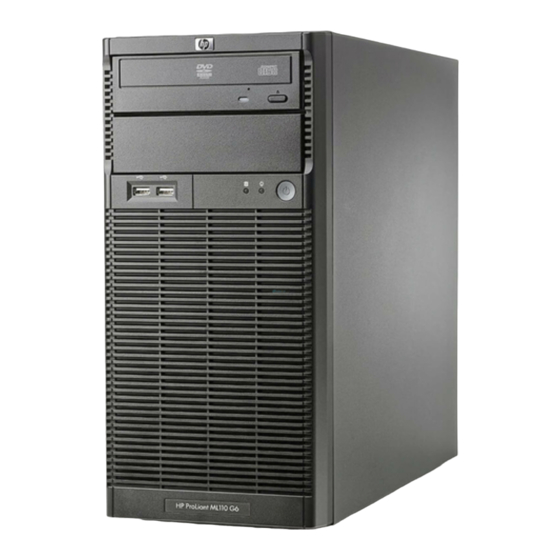
HP ProLiant ML110 G6 Installation Sheet
Hide thumbs
Also See for ProLiant ML110 G6:
- User manual (112 pages) ,
- Datasheet (4 pages) ,
- Maintenance and service manual (115 pages)
Table of Contents
Advertisement
Quick Links
HP ProLiant ML1 10 G6
Server
Installation Sheet
Part number: 580147-002
March 2010 (Second edition)
Configuring the server
1.
Connect all peripherals to your server.
o
Keyboard
Mouse
o
Monitor
o
2.
Determine the server BIOS version.
a. Power up the server.
b. Press the Esc key at the HP logo screen, and then press the
Pause key to halt screen movement.
c.
Note the server BIOS version.
d. Verify the server BIOS version against the latest BIOS
version listed for this server on the HP website:
http://www.hp.com
e. If you do not have the latest BIOS, update the BIOS now.
Refer to the server's Server Maintenance and Service
Guide available on the HP website: http://www.hp.com
Default boot priority
By default, the server searches for boot devices in the following
order:
1.
Removable devices
2.
CD-ROM/DVD-ROM drive
3.
Hard drive
4.
Embedded NIC, PXE (Preboot Execution Environment—remote
boot over LAN)
Server configuration guidelines
Read the following items before performing any of the installation
procedures described in later sections.
WARNING: Failure to properly turn off the system power
before you open the server or before you start removing
or installing hardware components may cause serious
damage as well as bodily harm.
WARNING: To reduce the risk of personal injury from
hot surfaces, allow the chassis and any installed
hardware component to cool before touching them.
CAUTION: Observe the ESD precautions, pre- and post-
installation procedures, and proper cabling management
described in Chapter 2 of the server's Maintenance and
Service Guide when performing any installation
procedure.
Identifying server components
Front panel components
Item
Component
Item
Component
1
Optical disc drive (ODD)
6
External ambient thermal
sensor
2
ODD manual eject hole
7
HDD EMI shield thumbscrew
3
ODD eject button
8
HDD EMI shield
4
Power button
9
2
nd
removable media drive
bay EMI shield
5
USB ports
NOTE: The location of items 2 and 3 may vary depending on the model of
the installed removable media drive.
Rear panel components
Item
Component
Item
Component
1
Kensington lock notch
10
Management NIC port (RJ-45)
2
Cable lock provision notch
11
Video port
3
Access panel thumbscrew
12
Serial port
4
Expansion slot cover retainer
13
USB ports
thumbscrew
5
Expansion slot cover retainer
14
Embedded NIC port (RJ-45)
6
Expansion slot 1 cover
15
PS/2 keyboard port
7
Expansion slot 2 cover
16
PS/2 mouse port
8
Expansion slot 3 cover
17
Power supply cable socket
9
Expansion slot 4 cover
System board components
Item
Code
Component
1
ATXPWRCN2
4-pin ATX processor power connector
2
DIMM4B
Channel B 1
st
DDR3 DIMM slot
3
DIMM3D
Channel B 2
nd
DDR3 DIMM slot
4
DIMM2A
Channel A 1
DDR3 DIMM slot
st
5
DIMM1C
Channel A 2
nd
DDR3 DIMM slot
6
ATXPWRCN1
24-pin ATX system board power connector
7
CPU1
Processor
8
CPUFAN1
CPU heatsink fan connector
9
PCHSW1
System configuration switch
10
FPCN1
Power button / front panel LED cable connector
11
SATA1
1
st
HDD SATA cable connector
12
SATA2
2
nd
HDD SATA cable connector
13
SATA3
3
rd
HDD SATA cable connector
14
SATA4
4
th
HDD SATA cable connector
15
SATA5
1
st
ODD SATA cable connector
16
SATA6
2
nd
ODD SATA cable connector
17
USBCONN2
Internal USB connector for STD USB
18
USBCONN3
Internal USB connector for tape device
19
FPUSBCONN1
Front panel USB port connector
20
HDDLEDCN1
External SAS HDD LED cable connector
21
TPMCN1
TPM (Trusted Platform Module) connector
22
Full-height
Full-height/full-length PCIe Gen2 x16 slot (x16)
full-length Slot 4
PCIe x16 (16)
45W
23
Full-height
Full-height/full-length PCIe Gen1 x8 slot (x4)
full-length Slot 3
PCIe x8 (4)
25W
24
Full-height
Full-height/full-length 32-bit/33 MHz PCI slot
full-length Slot 2
PCI 32-bit
33 MHz 25W
25
THERSNRCN1
Cable connector for the external ambient thermal
sensor
Advertisement
Table of Contents

Summary of Contents for HP ProLiant ML110 G6
-
Page 1: Identifying Server Components
External ambient thermal DIMM3D Channel B 2 DDR3 DIMM slot sensor b. Press the Esc key at the HP logo screen, and then press the Pause key to halt screen movement. DIMM2A Channel A 1 DDR3 DIMM slot ODD manual eject hole HDD EMI shield thumbscrew Note the server BIOS version. -
Page 2: Opening The Server
The information contained herein is subject to change without notice. The performance, install in the DIMM2A and DIMM4B slots. only warranties for HP products and services are set forth in the express warranty statements accompanying such products and services. Nothing herein should be construed as constituting an additional warranty.


Need help?
Do you have a question about the ProLiant ML110 G6 and is the answer not in the manual?
Questions and answers