
Related Manuals for Synrad UC-2000

Summary of Contents for Synrad UC-2000
- Page 1 ® 4600 Campus Place Mukilteo, WA 98275 1.800.SYNRAD1 tel 1.425.349.3500 fax 1.425.349.3667 e-mail synrad@synrad.com web www.synrad.com...
- Page 3 UC-2000 Universal Laser Controller Operator’s Manual Version 3.0 December 2010 Part number 900-18128-02 ® 4600 Campus Place Mukilteo, WA 98275 1.800.SYNRAD1 tel 1.425.349.3500 fax 1.425.349.3667 e-mail synrad@synrad.com web www.synrad.com...
-
Page 5: Table Of Contents
Setting PWM frequency ................2-6 Setting gate logic ..................2-7 Setting max PWM percentage ..............2-8 Setting lase on power-up .................2-8 Setting REMOTE (RS-232) protocol ............. 2-9 Setting option 2–3 ...................2-10 Save and exit ...................2-10 Factory default settings ................2-10 Synrad UC-2000 operator’s manual... - Page 6 Serial Port connector ................3-11 Host serial port configuration ..............3-13 REMOTE checksum commands ...............3-13 Connector pinouts ..................3-21 Laser connector ..................3-21 Closed loop (C/L) connector ..............3-21 General specifications ................3-22 UC-2000 package outlines ..............3-23 Troubleshooting Troubleshooting ..................4-2 Synrad UC-2000 operator’s manual...
- Page 7 Appendix A Closed Loop Stabilization Kit ..............A-2 Introduction ....................A-2 Safety precautions ..................A-2 Connecting ....................A-3 Operation ....................A-4 Closed loop specifications ................A-4 Appendix B Non-checksum commands ..............B-2 REMOTE non-checksum commands ............B-2 Index Synrad UC-2000 operator’s manual...
- Page 8 Figure 3-5 Physical layout of RS-232 Serial Port connector ..3-11 Figure 3-6 RS-232 cable wiring diagram ......... 3-12 Figure 3-7 UC-2000 package outline dimensions ......3-23 Figure 3-8 UC-2000 panel mount package outline dimensions ................3-24 Figure A-1 Typical closed loop setup ..........A-3 Synrad UC-2000 operator’s manual...
- Page 9 Host serial port configuration .........3-13 Table 3-8 Laser connector pinouts ........... 3-21 Table 3-9 C/L connector pinouts ............3-21 Table 3-10 UC-2000 general specifications ........3-22 Table A-1 Closed loop general specifications ........ A-4 Table B-1 REMOTE Mode commands ........... B-3 Table B-2 REMOTE Lase commands ..........B-3...
- Page 10 Trademark/copyright information SYNRAD, Firestar, and Power Wizard are registered trademarks of SYNRAD, Inc. Evolution is a trademark of SYNRAD, Inc. All other trademarks or registered trademarks are the property of their respective owners. © 2005, 2009, 2010 by SYNRAD, Inc.
- Page 11 Return Authorization (RA) number is required; this number must be clearly marked on the outside of the shipping container in order for the unit to be properly processed. If replace- ment parts are sent to you, then you are required to send the failed parts back to SYNRAD for evaluation unless otherwise instructed.
- Page 12 Sales and Applications SYNRAD’s Regional Sales Managers work with customers to identify and develop the best laser solution for a given application. Because they are familiar with you and your laser application, use them as a first point of contact when questions arise. Our Regional Sales...
-
Page 13: Terms
Protective eyewear that blocks 10.6 µm wave- length CO laser radiation is available from SYNRAD. Synrad UC-2000 operator’s manual... - Page 14 1910, Subpart Z. Threshold Limit Values (TLV’s) published by the Ameri- can Conference of Governmental Industrial Hygienists (ACGIH). It may be necessary to consult with local governmental agencies regarding restrictions on the venting of process- ing vapors. Synrad UC-2000 operator’s manual...
- Page 15 This product contains components that are considered hazardous industrial waste. If a situ- ation occurs where the unit is rendered non-functional and cannot be repaired, it may be returned to SYNRAD, Inc. who, for a fee, will ensure adequate disassembly, recycling, and/or disposal of the product.
-
Page 16: Label Locations
December 01, 2004 4600 Campus Place, Mukilteo, WA 98275 (425)349-3500 Ser#: UC40336021891 MODEL: UC-2000 15–50 VDC, 35mA MFG: December 01, 2004 4600 Campus Place, Mukilteo, WA 98275 (425)349-3500 Ser#: UC40336021891 UC-2000 CE label location Figure 1 Synrad UC-2000 operator’s manual... -
Page 17: Agency Compliance
Agency c The UC-2000 Universal Laser Controller has been tested and certified to comply with cer- tain United States and European Union (EU) Directives. These Directives impose product performance requirements related to electromagnetic compatibility (EMC) and product safety characteristics for laser products. -
Page 18: Figure 2 European Compliance Mark
Agency compliance UC-2000 Universal Laser Controllers have demonstrated performance characteristics that have met or exceeded the requirements of the EMC directive 2004/108/EC. Table 1 contains a summary of EU performance requirements pertaining to the UC-2000 Universal Laser Controller. Table 1... - Page 19 Agency compliance RoHS compliance UC-2000 Universal Laser Controllers meet the requirements of the European Parliament and Council Directive 2002/95/EC on the Restriction of the Use of Certain Hazardous Substances in Electrical and Electronic Equipment, as amended by Decision 2005/618/EC establishing maximum concentration values for certain hazardous substances in electrical and electronic equipment.
-
Page 20: Declaration Of Conformity
EN 61000-4-4:1995 Electrical Fast Transient/Burst Immunity EN 61000-4-6:1996 Conducted RF Disturbances Immunity Corporate Officer: European Contact: Excel Technology Europe GmbH Münchner Str. 2a D-82152 Planegg Dave Clarke, President of SYNRAD, Inc. Germany Dated 01 July 2009 Synrad UC-2000 operator’s manual... -
Page 21: Getting Started
Controller for operation. The order of information presented in this section is the same as the order of tasks that you will need to perform. The best way to get the UC-2000 ready for operation is to start at Inventory and work your way through Connecting. -
Page 22: Inventory
Power/Control Cable – provides DC power to the UC-2000 and outputs tickle/Command signals to the laser. Wall Plug Transformer – provides 24 VDC to the UC-2000 Controller from a 100–240 VAC, 50–60 Hz wall plug outlet. BNC to BNC Control Cable – use with BNC Tee to connect Power/Control Cable to dual- tube lasers. -
Page 23: Introduction
Introduction The UC-2000 Universal Laser Controller is SYNRAD’s third-generation laser controller, a product which has evolved from years of experience with hundreds of SYNRAD laser control- lers currently being used in applications at customer sites throughout the world. Features UC-2000 features include: ■... -
Page 24: Mounting
Standard model The UC-2000 Universal Laser Controller’s rubber feet are designed for shelf or table-top mounting. If your application requires the UC-2000 to be securely fastened to a shelf or rack, perform the following steps: Remove at least two of the four 6–32 Phillips head screws holding the UC-2000’s rubber feet to the chassis. -
Page 25: Connecting
Plug the compact transformer into any 100–240 VAC, 50–60 Hz outlet. For other laser types, power the UC-2000 from any 15–50 VDC source capable of supplying 35 milliamperes (mA) of current. If you choose to supply DC voltage from an alternate power source, ensure that connector polarity to the miniature DC power plug is correct: the tip or inner sleeve polarity is positive (+);... - Page 26 3000 RF power supplies. The connections you have just completed are sufficient for manual operation and testing of the UC-2000 Controller. Refer to Initial start-up in the Operation chapter for start-up proce- dures. See UC-2000 control and Laser control in the Operation chapter for detailed information regarding UC-2000 operation and the various options for PWM laser control.
-
Page 27: Operation
Initial start-up – explains how to operate the UC-2000 Controller. ■ Setup – describes how to set UC-2000 operating parameters. ■ UC-2000 control – describes local and REMOTE control of the UC-2000. ■ Laser control – describes each of the UC-2000’s PWM control methods ■... -
Page 28: Controls And Indicators
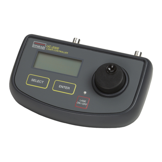
ON / OFF Figure 2-1 Control panel LCD Display – displays UC-2000 operating and setup parameters. Select Pushbutton – scrolls through menu selections. Enter Pushbutton – selects a menu item. Lase On/Off Pushbutton – press to toggle the laser On or Off using the current operating parameters. -
Page 29: Rear Panel
Gate Connector – input BNC connector for applications using external gating signals to gate the laser beam on and off. Note: All BNC connectors on the UC-2000 Controller are wired so that the signal is con- nected to the center pin and the signal return, or ground, is connected to the BNC shell. -
Page 30: Lcd Display
Controls and indicators LCD display When power is first applied to the UC-2000 Controller, the firmware screen (shown in Figure 2-3) appears and displays the current firmware version. * * * * * * * * * * *... -
Page 31: Initial Start-Up
PWM duty cycle. The curve of laser output versus PWM duty cycle also varies slightly when different PWM frequencies are used. Press the Lase On/Off pushbutton to halt lasing. The red Lase indicator on the UC-2000 and the laser’s LASE indicator will both turn off. -
Page 32: Setup
Setting PWM frequency The UC-2000 sends Pulse Width Modulation (PWM) signals to the laser at user-selectable frequencies of 5, 10, or 20 kHz. The standard modulation frequency of 5 kHz works well in most laser applications and provides the greatest depth of modulation (Figure 3-2 in the Tech- nical Reference chapter). -
Page 33: Setting Gate Logic
Gate connector (laser output enabled when gate input is active) causes the UC-2000 to rapidly switch the laser on and off. The laser’s “on” power level is set by the UC-2000’s PWM Adj Knob or by external ANC, ANV, or REMOTE inputs. When laser “off”... -
Page 34: Setting Max Pwm Percentage
Enter to exit Setup mode and write operating parameters to memory. Setting lase on power-up Normal operation of the UC-2000 Controller requires an operator to press the Lase On/Off pushbutton to enable lasing after Controller power-up. This safety feature prevents inadver- tent laser operation in the event that power is cycled off and then on again such as during a power failure. -
Page 35: Setting Remote (Rs-232) Protocol
This indicates that the new Lase On Power-Up setting is saved into memory. Power down the UC-2000 Controller. The next time the UC-2000 is powered up, the Lase indicator will illuminate and the laser will begin firing immediately at the commanded power setting (provided that the Gate input is active). -
Page 36: Setting Option 2-3
On exit, the Controller beeps twice to indicate that operating parameters were successfully saved to non-volatile memory. Factory default settings Table 2-1 lists factory default settings for the UC-2000 Controller. Table 2-1 Factory default settings... -
Page 37: Uc-2000 Control
UC-2000 control You can control the UC-2000 using either of two methods: local control, using panel knobs and buttons; or REMOTE control, using RS-232 serial port commands. Both methods allow you to control laser operation including output power adjustment and On/Off status. -
Page 38: Remote (Rs-232) Control
UC-2000 control Autosave feature Six seconds after the last pushbutton or PWM Adj Knob operation (in local UC-2000 con- trol), the Controller automatically saves the current mode settings and PWM power percent- age into non-volatile memory. After saving operational settings, the Controller beeps twice to indicate success. -
Page 39: Figure 2-6 Remote Mode
UC-2000 control Note: In response to a status request, the UC-2000 can report status data to the RS-232 link while it is in any local control or REMOTE control mode. M O D E : O T E S E T :... -
Page 40: Laser Control
During standby operation (power applied to the UC-2000 Controller with the Lase indicator off), the UC-2000 sends 5 kHz “tickle” pulses to pre-ionize laser gas to just below the lasing threshold. Tickle allows the laser to respond almost instantaneously to Command signals as the beam is switched off and on during laser operations. -
Page 41: Figure 2-7 Manual Mode
PWM Adj Knob. Rotating the knob changes laser output power from zero to maximum by varying the UC-2000’s PWM output from 0 to 95 (or 99) percent in 0.5% steps. When operating the UC-2000 using REMOTE control, adjust laser power “manually” by sending the appropriate command and data bytes via the RS-232 serial port. -
Page 42: Figure 2-9 Anv Mode
Closed loop power control is available for SYNRAD lasers with a factory installed Closed Loop Stabilization Kit. See Appendix A for details. When operating the UC-2000 using local control, Figure 2-10, adjust the laser’s desired output power (regulated setpoint) using the PWM Adj Knob. When operating the UC-2000 using REMOTE control, adjust the laser’s desired output power (regulated setpoint) “manually”... -
Page 43: Figure 2-10 Man. Closed Mode
MAN. CLOSED mode ANV CLOSED Closed loop power control is available for SYNRAD lasers with a factory installed Closed Loop Stabilization Kit. See Appendix A for details. In analog voltage closed loop control (ANV CLOSED) mode, Figure 2-11, the laser’s desired output power (regulated setpoint) is controlled by an external analog voltage. -
Page 44: Gate Input
(PLC). Gate control is available in any of the five UC-2000 operating modes. See External control in the Technical Reference chapter for descriptions of gate signal connections and specifications. -
Page 45: Technical Reference
Use information in this section as a technical reference for the UC-2000 Uni- versal Laser Controller. This sections contains the following information: Control signals – explains the control signals generated by the UC-2000. ■ External control– explains how to connect externally-generated control ■... -
Page 46: Control Signals
Control signals Tickle pulse All SYNRAD lasers require a tickle pulse, a 5 kHz signal with a 1 microsecond (µs) pulse width, which is normally delivered by the UC-2000 Controller. Tickle pulses pre-ionize the laser gas to just below the lasing threshold so that any further increase in pulse width adds enough energy to the plasma to cause laser emission. -
Page 47: Command Signal
Base frequency is the repetition rate of the PWM Command signal. The standard base fre- quency is 5 kHz, which has a pulse period of 200 µs. The UC-2000 provides user-selectable PWM frequencies of 5 kHz, 10 kHz (100 µs period), or 20 kHz (50 µs period). -
Page 48: Table 3-1 Command Signal Output Specifications
Command signal parameters When operating in MANUAL or MAN. CLOSED mode using local control, set the required PWM Command signal (duty cycle percentage) using the UC-2000’s PWM Adj Knob. When operating in MANUAL or MAN. CLOSED mode using REMOTE control, the PWM Command signal is controlled by a computer or PLC sending PWM or closed loop SET com- mand and data bytes via an RS-232 serial interface. -
Page 49: External Control
Each method of external control is described below. Note: All BNC connectors on the UC-2000 are wired so that the signal is connected to the center pin and the signal return, or ground, is connected to the BNC shell. -
Page 50: Table 3-2 Gate Input Specifications
Gate connector in order to fire the laser. The UC-2000’s gate input function has two settings: Gate Pull Up (normally on) and Gate Pull Down (normally off). When Gate Pull Up is chosen, UC-2000 circuitry connects an internal resistor to pull the Gate input up to an active level, which means that the laser will fire without a gate signal present when the Lase On/Off pushbutton is pressed. -
Page 51: Analog Control
Analog control Several methods for external analog control of PWM power percentage are available through the UC-2000. ANC and ANV control methods are fully described below; computer or PLC control of PWM is discussed later in this section. Analog current control Analog current (ANC) control of laser power is accomplished by using a 4–20 mA current... -
Page 52: Table 3-4 Analog Voltage Specifications
Closed loop control section. See Table 3-4 for analog voltage signal specifica- tions. Follow the steps below to set your UC-2000 Controller for ANV control: Press the Select pushbutton until Line 4 in the LCD display shows “FUNC: ANV”. -
Page 53: Closed Loop Control
In manual closed loop (MAN. CLOSED) mode, the desired regulated setpoint is set using the PWM Adj Knob (local control) or by sending command and data bytes to the UC-2000 Con- troller’s RS-232 serial port (REMOTE control). Closed loop power regulation is maintained by the laser’s closed loop kit. -
Page 54: Table 3-5 Analog Voltage Closed Loop Specifications
Table 3-5 shows analog voltage closed loop signal specifications. Follow the steps below to set your UC-2000 Controller for ANV CLOSED control: Press the Select button until Line 4 in the display shows “FUNC: ANV CLOSED”. -
Page 55: Remote Control
Send REMOTE commands as described below to remotely operate the UC-2000. Serial Port connector Connect to the UC-2000’s Serial Port connector using a standard serial cable. Figure 3-5 illustrates the physical layout of the Serial Port connector on the rear of the UC-2000 Laser Controller. Pin 6... -
Page 56: Figure 3-6 Rs-232 Cable Wiring Diagram
Receive Data (RD) Signal Ground (SG) If you choose to build a custom length serial cable to connect between the host’s serial port and the UC-2000 Controller’s Serial Port connector, refer to Figure 3-6; it illustrates a typical three-wire serial cable. HOST... -
Page 57: Host Serial Port Configuration
REMOTE control Host serial port configuration In order to communicate through the UC-2000’s RS-232 serial port, you must configure the host computer’s (or PLC’s) serial port protocol. Table 3-7 provides RS-232 configuration speci- fications for the UC-2000 Laser Controller. - Page 58 The following command sets are available for controlling the UC-2000 from a host computer or PLC. Each command set listed below is described on the following pages.
- Page 59 Command byte. Example: Send the following bytes to set PWM frequency to 20 kHz: 5B Upon completion of a valid command request, the UC-2000 returns a single byte, AA , as an acknowledgment of success. A NAK response (3F ) is sent when no valid command or check- sum value is received within one second of the STX byte or if the checksum value is incorrect.
- Page 60 <Checksum> = a checksum byte created by performing a One’s compliment (bit inversion) of the Command byte. Example: Send the following bytes to operate in ANV mode: 5B Upon completion of a valid command request, the UC-2000 returns a single byte, AA , as an acknowledgment of success. A NAK response (3F ) is sent when no valid command or check- sum value is received within one second of the STX byte or if the checksum value is incorrect.
- Page 61 BA Example: Send the following bytes to set a PWM output of 63%: 5B Upon completion of a valid command request, the UC-2000 returns a single byte, AA , as an acknowledgment of success. A NAK response (3F ) is sent when no valid command or check- sum value is received within one second of the STX byte or if the checksum value is incorrect.
- Page 62 <Checksum> = a checksum byte created by performing a One’s compliment (bit inversion) of the Command byte. Example: Send the following bytes to enable lasing: 5B Upon completion of a valid command request, the UC-2000 returns a single byte, AA , as an acknowledgment of success. A NAK response (3F ) is sent when no valid command or check- sum value is received within one second of the STX byte or if the checksum value is incorrect.
- Page 63 REMOTE control Status Request command Note: The UC-2000 can report its status to the RS-232 link while in any operating mode. The Command/Response format for requesting UC-2000 Controller status is: Status Request Response ACK<Status Byte1><Status Byte2><PWM Byte><Power Byte><Checksum>...
- Page 64 In closed loop mode, the PWM Byte returns the commanded SET value, and the Power Byte returns the actual regulated POWER shown in the display. Power byte val- ues are valid only when operating the UC-2000 in MAN. CLOSED or ANV CLOSED closed loop modes.
-
Page 65: Connector Pinouts
Connector pinouts Laser connector The Laser connector on the rear of the UC-2000 is a four-pin mini-DIN type. Table 3-8 shows Laser connector pinouts. The PWM cable is a type RG174/U coaxial 50 Ohm cable. Table 3-8 Laser connector pinouts... -
Page 66: General Specifications
@10 VDC (5, 10, or 20 kHz) impedance – 10 kOhms Remote Input: software commands Output: Manual, ANC, ANV, Man. Closed Loop or via RS-232 serial port ANV Closed Loop mode signal * Specifications subject to change without notice. Synrad UC-2000 operator’s manual... -
Page 67: Uc-2000 Package Outlines
UC-2000 package outlines Figure 3-7 UC-2000 package outline dimensions Synrad UC-2000 operator’s manual... -
Page 68: Figure 3-8 Uc-2000 Panel Mount Package Outline
UC-2000 package outlines UC-2000 panel mount package outline dimensions Figure 3-8 Synrad UC-2000 operator’s manual... -
Page 69: Troubleshooting
Use information in this section to troubleshoot of your UC-2000 Universal Laser Controller. This section contains the following information: Troubleshooting – describes how to troubleshoot common problems. ■ Synrad UC-2000 operator’s manual... - Page 70 Troubleshooting If your UC-2000 Controller fails to operate properly, first check the following items: ■ Is DC power available? ■ Is it within the specified voltage range? See General Specifications in the Technical Refer- ence chapter. ■ Is the Controller set for the proper control method – local or REMOTE? ■...
- Page 71 Static discharge during storage or transportation has caused one or more of the saved set- tings in EEPROM memory to change while the UC-2000 was powered down. Reprogram the UC-2000 Controller to the settings last used in your application. It should function normally after settings are reset to their previous values.
- Page 72 Troubleshooting Symptom: ■ The UC-2000 Controller is configured for Lase On Power-Up (the Setup screen shows “LASE ON PWR-UP Y”), but the laser does not fire when the UC-2000 Controller and laser are powered up. Possible Causes: ■ After setting Lase On Power-Up to “Y” (Yes), an active lasing state must be saved.
- Page 73 Connecting – describes how to connect the closed loop kit to your UC- ■ 2000 Controller. Operation – describes closed loop operation. ■ Closed loop specifications – provides technical specifications for the ■ Closed Loop Stabilization Kit. Synrad UC-2000 operator’s manual...
-
Page 74: Closed Loop Stabilization Kit
Closed Loop Stabilization Kit Introduction The Closed Loop (C/L) Stabilization Kit is available for 10 W and 25 W SYNRAD lasers and must be installed and calibrated at the factory. The closed loop kit provides an effective, reliable method of stabilizing laser power output by optically sampling the beam and providing feedback to adjust the PWM duty cycle percentage of the UC-2000’s output PWM Command... -
Page 75: Connecting
UC-2000’s 8-pin mini-DIN C/L connector. If required, connect a gating signal to the UC-2000’s Gate BNC connector. If required, connect an ANV signal from your analog voltage source to the UC-2000’s ANV/ANC BNC connector. -
Page 76: Operation
Controller to maintain full dynamic power regula- tion. Within the dynamic response time of the system, the UC-2000 Controller can be gated from an external, low-frequency signal source through the Gate connector. - Page 77 Use information in this section to operate the UC-2000 in REMOTE control using the original non-checksum RS-232 communication protocol. This sections contains the following information: REMOTE non-checksum commands – describes how to use the UC-2000’s ■ original non-checksum commands when using RS-232 serial commands.
-
Page 78: Non-Checksum Commands
PC or PLC. See REMOTE control in the Technical Reference chapter for information on formatting checksum serial commands. The following non-checksum command sets are available for controlling the UC-2000 from a host computer or PLC. Most command sets consist of a single hexadecimal byte (designated by the suffix h), except for the PWM/SET percentage command which consists of two bytes, a command byte and a data byte. -
Page 79: Table B-1 Remote Mode Commands
REMOTE Setup commands Function Command Response Set PWM Freq=5K Set PWM Freq=10K Set PWM Freq=20K Set Gate Pull Up Set Gate Pull Down Set Max PWM=95% Set Max PWM=99% Enable Lase On Power-up Disable Lase On Power-up Synrad UC-2000 operator’s manual... -
Page 80: Table B-4 Remote Pwm (Or Set) Percentage Command
(8C ) after sending the 7F command byte. If the UC-2000 does not receive a data byte within six seconds of receiving a 7F command byte, the PWM or SET percentage input command is halted. Note: Commanding a PWM or SET percentage of 63 (7E ) is interpreted as a “Get Status”... -
Page 81: Table B-5 Remote Status Request Command
Non-checksum commands Table B-5 REMOTE Status Request command Note: The UC-2000 can report its status to the RS-232 link while in any operating mode. Function Command Response Get status ; Status Byte1; Status Byte2; PWM Byte; Power Byte... - Page 82 This page intentionally left blank Synrad UC-2000 operator’s manual...
- Page 83 C/L connector 2-3, 3-9, 3-10, 3-17, description, 2-2 illustration, 2-2 pinouts, 3-21 Control signals 3-2–3-4 Caution Command signal, 3-3–3-4 definition, 1 Pulse Width Modulation, 3-2–3-3 tickle pulse, 3-2 label location, 4 Copyright information viii mark, 6 Synrad UC-2000 operator’s manual...
- Page 84 Declaration of Conformity 8 Gate logic 3-6, 4-2 Dimensions setting, 2-7 UC-2000 package outline, 3-23 Gate signal 2-7, 2-15, 3-5 UC-2000 panel mount package out- specifications, 3-6, 4-3 line, 3-24 General specifications Closed Loop Kit, A-4 UC-2000, 3-22 Enter pushbutton 2-2, 2-5, 2-6, 2-7,...
- Page 85 3-18 panel mount model, 1-4 mode commands, 3-16 PWM (SET) percentage command, 3-17 setting protocol, 2-9–2-10 Occupational Safety and Health Adminis- setup commands, 3-15 tration (OSHA) 3 status command, 3-19–3-20 Operating mode selection, 2-14–2-17 Synrad UC-2000 operator’s manual...
- Page 86 Setup screens 2-6 definition, 1 Specifications laser safety, 2 analog current, 3-7 personal injury, A-2 analog voltage, 3-8 protective eyewear, 1, 2-5, A-2 ANV closed loop, 3-10 radiation exposure, 3, A-2 Closed Loop Kit, A-4 Warranty information ix Synrad UC-2000 operator’s manual...
Need help?
Do you have a question about the UC-2000 and is the answer not in the manual?
Questions and answers