Table of Contents
Advertisement
Advertisement
Table of Contents

Related Manuals for Datron PRC1077


Summary of Contents for Datron PRC1077
- Page 1 PRC1077-MSOP PRC1077 Radio Set Operator Manual Datron World Communications Inc. Manual Part No. PRC1077-MSOP Release Date: March 2007 Revision: C 3030 Enterprise Court Vista, CA 92081, U.S.A. Phone: (760) 597-1500 Fax: (760) 597-1510 E-Mail: sales@dtwc.com www.dtwc.com...
- Page 3 Description of Changes Revision Letter Affected 6/1991 Original release 6/2006 Overall update to text and format. 3/2007 Changed cable part number part number from Page 2-22 C991611 to C991618. Figure 2-14 Added protective power cap to replacement parts Page 4-4 table. PRC1077-MSOP...
- Page 5 Software, documentation, and All rights reserved. any copies of each to Datron. This Software is licensed “AS IS” and Datron provides a war- Datron World Communications, Inc. ranty that covers the media upon which the Software is embed- This manual, as well as the software described in it, is ded for a period of 30 days from receipt of the product.
- Page 6 Remedies: Buyer’s sole remedies and the entire liability of Datron are set forth above. In no event will Datron be liable to Buyer or any other person for any damages, including any incidental or consequential damages,...
-
Page 7: Table Of Contents
Figure 4-1. PRC1077 Replacement Parts ........ - Page 8 PRC1077 Repeater Installation........
-
Page 9: Chapter 1: Introduction
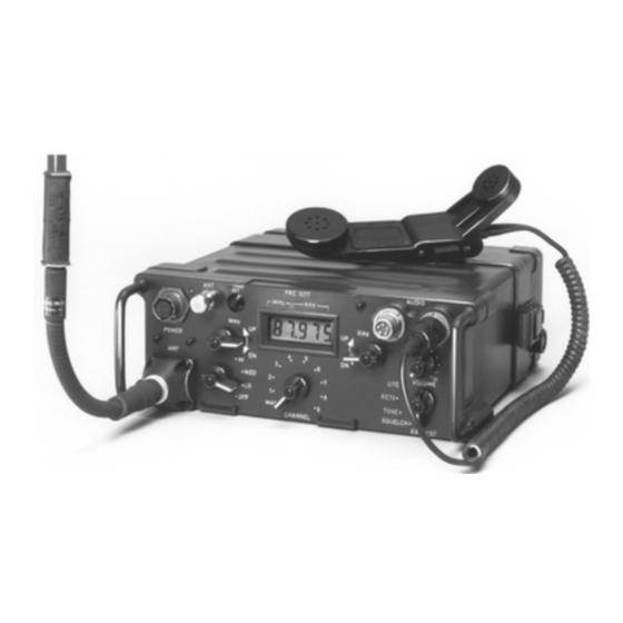
PRC1077 radio set can also be integrated into the VRC-64 and GRC-160 vehicular radio systems. The PRC1077 can be configured for manpack, mobile, and base applications in 5W or 50W output levels. The PRC1077 is supported with a full line of accessories such as: •... -
Page 10: Technical Specifications
0.5W, 2W, or 5W (selectable) Duty cycle Continuous service Harmonics –50 dB Receiver Sensitivity 10 dB SINAD for 0.3 µV input Squelch 150 Hz tone, carrier; selectable Audio 500 mW into 16 ohms; 50 mW at 150 ohms; 0 dBm into 600 ohms PRC1077-MSOP... - Page 11 MT1077, +12 Vdc or +24 Vdc versions; mounts to any vehicle Power supply PS1077 for portable use; UPF7000A-28 or UPF7000A-12 for base station Chargers PRC-BC4 (4-unit charger), PRC-PS (power supply or 2-unit charger), PRC-SPU-10 (solar power unit), PRC-HC-30 (hand crank generator) Converter AM1077CONV, 12 Vdc to 28 Vdc PRC1077-MSOP...
-
Page 13: Chapter 2: Installation
CHAPTER 2 INSTALLATION Unpacking The PRC1077 is shipped in a heavy-duty corrugated cardboard carton with the accessories packed in a separate carton. Do not discard the cartons and packing materials in case the equipment needs to be reshipped. Inspect the equipment for possible damage during shipment. Check all accessories against the packing list. - Page 14 To install the BB-LA6 battery into the PRC1077 (refer to the figure on page 2-3): Stand the PRC1077 on a level surface with the front panel facing down. Pull the two clamps out from the transceiver case to release and push down on the battery case.
-
Page 15: Figure 2-1. Bb-La6 Battery Installation
(at the transceiver back) and negative (–) applied to the A terminal. To avoid serious damage to the transceiver, do not change the battery polarity. The PRC1077 manpack system includes the LC-2 or ST-138 backpack. The lnstalling the LC-2 backpack is a lightweight tubular carrying frame with canvas straps. -
Page 16: Figure 2-2. Manpack Components
Hook the two belt straps to the combat belt. Shoulder strap ring (2) Shoulder straps Transceiver Retaining Straps Shoulder Strap Buckle (2) Retaining Strap Buckles (2) Cotton Duck Lower Strap (2) Metal Braces Belt Strap (2) Figure 2-2. Manpack Components PRC1077-MSOP... -
Page 17: Figure 2-3. Manpack Accessories
Screw AB-591/U flexible antenna base into the mount. Unfold the AT-271A/U by holding the base section (the heaviest section) and carefully whipping it outward. If all sections are not secure, insert the sections by hand. Screw the extended AT-271A/U antenna into the AB-591/U antenna base. PRC1077-MSOP... - Page 18 The plastic filling in the thread is designed to prevent the antenna from unscrewing, however, if the plastic wears, vibration can cause the antenna to become loose. Periodically tighten the antenna in the mount. PRC1077-MSOP...
-
Page 19: Figure 2-4. At-892/U Antenna Orientation In Various User Positions
Antenna horizontal (radiation directional and at right angles to antenna) Figure 2-4. AT-892/U Antenna Orientation in Various User Positions The PRC1077 manpack configuration uses the MHS handset, which is either a Installing the H-189/U or H-250/U military handset. Handset To install a handset on the PRC1077 front panel... -
Page 20: Mobile Installation
2: Installation Mobile Installation The PRC1077 can be integrated into 12 Vdc or 24 Vdc mobile applications with 5W or 50W output. Each configuration is designed for emergency rapid removal. 4242-MK2 C991577 4242-MK2 PRC1077 C991577 C991949 PRC1077 C991580 +24 Vdc... - Page 21 MT-1077 SET PWR connector (J4). Note: Make sure the POWER connector protective cap is attached to the PRC1077 transceiver front panel by a cord so it will not become lost. The protective cap grounds the connector when the cap is installed. If the protective cap is not installed or the C991949 cable is not installed and connected to the MT-1077 adapter, the PRC1077 will not operate.
-
Page 22: Figure 2-6. 5W 24 Vdc Mobile System With Oa3633/Vrc Adapter
MT-1029/VRC shock mount and clamp in place with the two mounting clamps. Slide the PRC1077 transceiver onto the OA3633/U adapter and clamp in place with the two mounting clamps. On the PRC1077, remove the protective cap from the POWER connector. -
Page 23: Figure 2-7. 50W 24 Vdc Mobile System
+24 Vdc source source MT-1077-24 Figure 2-7. 50W 24 Vdc Mobile System The PRC1077 50W mobile system can be used in 12 Vdc or 24 Vdc vehicular 50W System applications and requires a 50W RF power amplifier. Accessory Part Number... - Page 24 MT-1077 SET PWR connector (J4). Note: Make sure the POWER connector protective cap is attached to the PRC1077 transceiver front panel by a cord so it will not become lost. The protective cap grounds the connector when the cap is installed. If the protective cap is not installed or the C991949 cable is not installed and connected to the MT-1077 adapter, the PRC1077 will not operate.
-
Page 25: Figure 2-8. 50W 12 Vdc Mobile System
+12 Vdc MT-1077-12 source source Figure 2-8. 50W 12 Vdc Mobile System To install the PRC1077 into a 12 Vdc 50W mobile system (refer to the figure above): Without installing a battery, install the battery box onto the PRC1077 transceiver case (refer to "Installing the Battery"... - Page 26 MT-1077 SET PWR connector (J4). Note: Make sure the POWER connector protective cap is attached to the PRC1077 transceiver front panel by a cord so it will not become lost. The protective cap grounds the connector when the cap is installed. If the protective cap is not installed or the C991949 cable is not installed and connected to the MT-1077 adapter, the PRC1077 will not operate.
-
Page 27: Fixed Base Installation
Figure 2-9. 5W Fixed Base System The PRC1077 5W fixed base system uses the same adapters and mounts as the 5W Systems mobile systems, however the system includes a 28 Vdc power supply that connects to a 110 Vac source. - Page 28 MT-1077 SET PWR connector (J4). Note: Make sure the POWER connector protective cap is attached to the PRC1077 transceiver front panel by a cord so it will not become lost. The protective cap grounds the connector when the cap is installed. If the protective cap is not installed or the C991949 cable is not installed and connected to the MT-1077 adapter, the PRC1077 will not operate.
-
Page 29: Figure 2-10. 50W Fixed Base System
Figure 2-10. 50W Fixed Base System The PRC1077 50W fixed base system uses the same adapters and mounts as 50W Systems the mobile systems, however the system includes a 28 Vdc power supply that connects to 110 Vac source. The fixed base system also uses the same RF amplifier and converter as the mobile system. - Page 30 MT-1077 SET PWR connector (J4). Note: Make sure the POWER connector protective cap is attached to the PRC1077 transceiver front panel by a cord so it will not become lost. The protective cap grounds the connector when the cap is installed. If the protective cap is not installed or the C991949 cable is not installed and connected to the MT-1077 adapter, the PRC1077 will not operate.
-
Page 31: Battery Charger Installation
The PRC-PS can operate both as an external power supply and as a battery PRC-PS Power charger, powering a PRC1077 and recharging a BB-LA6 battery at the same Supply/Battery time. The PRC-PS does not provide power but derives power from either a Charger 24 Vdc power source or a 115/230 Vac (internally strappable) power source. -
Page 32: Figure 2-12. Prc-Bc4 Multiple Battery Charger
2: Installation To recharge a BB-LA6 battery and power a PRC1077 at the same time (refer to the figure on page 2-19): 1. Connect the C991608 cable to the PRC-PS POWER SET connector (J1) and to the PRC1077 POWER connector. -
Page 33: Figure 2-13. Prc-Hc-30 Hand Crank Generator With Battery Installed
Allow about 6 hours to recharge a battery discharged to 20% of capacity. The PRC-HC-30 Hand Crank Generator can recharge a BB-LA6 battery PRC-HC-30 directly or while installed in a PRC1077. As the name indicates, the Hand Crank PRC-HC-30 is a mechanical hand-crank recharging device. -
Page 34: Figure 2-14. Prc-Hc-30 Hand Crank Generator With Battery Connected Directly
To recharge a BB-LA6 battery: 1. Unfold the PRC-SPU-10 Solar power generator and position it for maximum exposure to the sun. Connect the C991613 cable to the PRC-SPU-10 and to the PRC1077 with a BB-LA6 battery installed (refer to the figure... -
Page 35: Figure 2-16. Prc-Spu-10 Solar Power Generator With Battery Connected Directly
2: Installation BB-LA6 C991617 PRC-SPU-10 Figure 2-16. PRC-SPU-10 Solar Power Generator with Battery Connected Directly PRC1077-MSOP 2-23... -
Page 37: Chapter 3: Operation
CHAPTER 3 OPERATION Quick Start For basic operation, the PRC1077 needs a battery, an antenna, and a handset. To operate the PRC1077: 1. Install a fully charged battery. Install an antenna. Install a handset. Tuning Tuning Power Antenna Channel Control... -
Page 38: Settings, Indications And Connections
Receiver squelched - no background noise, audio only when signal is received. TONE Receiver squelched - no background noise, audio only on 150-MHz tone. Transmitter is modulated with 150 MHz tone. RETX Permits radio retransmission operation. LITE Momentarily back-lights frequency display. This lever position is spring loaded. PRC1077-MSOP... - Page 39 Volume Connectors provide connections for handsets and antennas. Connectors Connector Function/Action AUDIO Provides connection for handset or retransmission cable to transceiver. Provides connection for AT-271A/U or AT-892/U antenna. ANT (BNC) Provides connection for a fixed base or vehicular antenna. PRC1077-MSOP...
-
Page 40: Presetting Channel Frequencies
Presetting Channel Frequencies The PRC1077 stores up to 10 different frequencies. These frequencies remain in memory even if the battery pack is disconnected. Channels 1 to 9 are preset channels; however, the last frequency entered in the MAN channel is also retained in memory. -
Page 41: Jamming Recognition And Identification
00.000 MHz. Release the Tuning control MHz and the CHAN SET button. Semi-duplex operation is when the PRC1077 transmits and receives on Setting Different different frequencies. This type of setup is typically used for operating... -
Page 42: Radio Set Compatibility
When jamming is first detected, try the following checks to reduce the effects: Anti-Jamming Action Position the PRC1077 to make use of nearby obstructions to act as a screen against the jamming source. Experiment with different locations as the interference signal strength may vary substantially over very short distances. -
Page 43: Voice Security
3: Operation The PRC28 operates from 30 MHz to 42 MHz, leaving the PRC1077 with an unusable frequency range from 43 MHz to 87.975 MHz when communicating with the PRC28 transmitter. These unusable frequencies can provide security and protection from jamming if an enemy is using a PRC77 or PRC28 transmitter. -
Page 45: Chapter 4: Maintenance
• Perform the Operational Checklist. The following is a recommended procedure for weekly preventative maintenance to keep the PRC1077 and accessories in good working condition. • Inspect the handset cable for fraying, cuts, kinks and broken insulation. • Inspect all cloth items for fraying and tears. - Page 46 Make the following operational checks before and after using the PRC1077. If Operational the PRC1077 or any accessory fails to function correctly report the failure to Checklist technical personnel.
-
Page 47: Figure 4-1. Prc1077 Replacement Parts
4: Maintenance 11. The PRC1077 is designed with four internal test bands selected automatically by the microprocessor. Perform steps 8 and 9 in each of the four frequency band ranges listed below: • 30 MHz to 39 MHz • 40 MHz to 51.975 MHz •... -
Page 48: Replacement Parts
4: Maintenance Replacement Parts If a PRC1077 part is damaged, the following table provides a list of parts and part numbers for ordering replacement parts. Part Number Description 610080-A Protective dual audio connector cap 610085 Protective BNC cap 610087-A Protective antenna cap... -
Page 49: Appendix Aradio Relay And Repeaters
20 or 30 miles are easily achievable. Unfortunately, locating transceivers on elevated sites is not always possible. A relay system uses two PRC1077 positioned on elevated sites to relay signals. The two transceivers are connected using the MK-456/GRC Retransmission Cable Kit. -
Page 50: Repeater Operation
(refer to the Frequency Interference Chart on page A-4). The PRC1077 transmitter is compatible with the PRC77, so both types of transmitters can be used to create a radio relay system. Dedicated Receiver A dedicated repeater is a receiver/transmitter combination specifically designed to be used in a repeater system. -
Page 51: Prc1077 Repeater Installation
These factors help ensure the best service area coverage. PRC1077 Repeater Installation When using the PRC1077 in a repeater system, use the 1077 Retransmission Repeater Cable Kit to connect the two radio sets. The 1077RETRAN includes a 50-foot cable with connectors to connect two PRC1077 transceivers together. -
Page 52: Figure A-1. Frequency Interference Chart
40 MHz 30 MHz 30 MHz 40 MHz 50 MHz 60 MHz 70 MHz 80 MHz 88MHz RECEIVE FREQUENCY Figure A-1. Frequency Interference Chart PRC1077 RADIO SET (see NOTE 2) RELAY SITE CX-4656/GRC (see NOTES 1 and 4) 50 FT.
Need help?
Do you have a question about the PRC1077 and is the answer not in the manual?
Questions and answers