Table of Contents
Advertisement
Advertisement
Table of Contents

Related Manuals for AXYS Intellivox-DC115

Summary of Contents for AXYS Intellivox-DC115
-
Page 1: Installation Manual
Installation Manual ® AXYS Intellivox - DC/DS/DSX 115, 180, 280, 430 & 500 models... -
Page 2: Reference To Statements Of Conformity
AXYS ® Intellivox Installation Manual REFERENCE TO EC STATEMENT OF CONFORMITY This document confirms that products manufactured by USER’S NOTICE AND DISCLAIMER: Duran Audio bearing the CE label meet all the requirements No part of this manual including the software described in... -
Page 3: Table Of Contents
AXYS ® Intellivox Installation Manual TABLE OF CONTENTS Reference to Statements of Conformity ....2 User’s Notice and disclaimer ......2 1. -
Page 4: Important Safety Instructions
AXYS ® Intellivox Installation Manual 1. IMPORTANT SAFETY INSTRUCTIONS This symbol is intended to alert you to the 12) Use only with the cart, stand, tripod, bracket or presence of uninsulated dangerous voltages table specified by the manufacturer, or sold with the within the product's enclosure that may be of apparatus. -
Page 5: Introduction
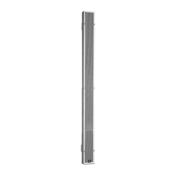
The AXYS ® Intellivox is a type of loudspeaker known as an ® This manual applies to the following AXYS Intellivox active DSP-controlled loudspeaker array, which utilises the models: principle of multiple, individually-driven loudspeaker drive Intellivox-DC115 and DS115 (fig.1a) -
Page 6: What's In The Packaging
AXYS ® Intellivox Installation Manual fig.2 A standard option applicable to all models is the position within the housing of the electronics module, which may either be at the top or bottom of the housing. The position is relevant to the installation procedure as the “acoustic Reference point for centre”... -
Page 7: Installation Guide
(DDA = Digital Directivity Analysis, Depending on the specific access issues, it may be better ® the AXYS proprietary simulation and optimisation to ensure that these cables are in place and correctly software for these products*). This procedure will have terminated “ready-to-plug-in”... -
Page 8: Connector And Wiring Details
AXYS ® Intellivox Installation Manual necessary to upload the correct settings for each unit to determined threshold. The frost protection thresholds can obtain the desired acoustic coverage. Once this has been be set using WinControl. If this function is required, an... -
Page 9: Ac Mains
AXYS ® Intellivox Installation Manual AC MAINS The Intellivox is equipped with a 3-pin IEC mains connector with an integral fuse holder. Only ever replace the fuse with one of the same type and rating. Be sure that the mains voltage stated on the unit complies with the local standard before connecting the Intellivox to the mains supply. -
Page 10: Wago Connectors
AXYS ® Intellivox Installation Manual WAGO CONNECTORS 3) Using the wire insertion tool supplied as shown below, All other Intellivox connections are made via the four on- open the clamp contact in the connector shell by pressing board WAGO Type 231 multi-pin connectors. These are: inwards towards the shell. -
Page 11: Audio Inputs
LINE 1 - cable consisting of a twisted pair and an overall screen. The LINE 1 SCN ® audio source(s) (e.g. the AXYS Octadrive) should have a Balanced source output (e.g. XLR) low impedance balanced output. The nominal line input level is 0 dBV. -
Page 12: Network Connection
AXYS ® Intellivox Installation Manual NETWORK CONNECTION Note that the transmit (Tx) and receive (Rx) balanced data The RS-485 network connection should be wired if either lines must be wired via their own twisted pairs. i) the Intellivox is to be constantly monitored in operation,... -
Page 13: Fault Monitoring/Fan Relay Connector
AXYS ® Intellivox Installation Manual FAULT MONITORING/FAN RELAY CONNECTOR Fault Monitoring The pinout of this connector is as follows: The Intellivox’s internal Failure Relay is energised in normal operation (COM connected to NC). Power failure or a pre- defined fault condition causes the relay to release, when COM will be shorted to NO. -
Page 14: External Ambient Spl/Temperature Sensor
AXYS ® Intellivox Installation Manual EXTERNAL AMBIENT SPL/TEMPERATURE SENSOR The pinout of this connector is as follows: External Ambient SPL Sensor The Intellivox incorporates an autogain algorithm which intelligently alters the volume of the audio according to the ambient noise level. An internal microphone is fitted to monitor the ambient noise level in the gaps in programme material. -
Page 15: Mechanical Installation
AXYS ® Intellivox Installation Manual MECHANICAL INSTALLATION Acoustic Centre Mounting an Intellivox loudspeaker is a straightforward procedure, but it is essential to understand that the height of the unit above floor level is extremely critical. The “correct operational height” is defined as part of the... -
Page 16: Mounting Options
AXYS ® Intellivox Installation Manual Mounting Options The Intellivox has two or three (depending on the model) of the enclosure by the four M5 pan head screws instead of attachment points at the rear of the enclosure; the device the standard brackets. Two versions of swivel bracket are... -
Page 17: Mounting Procedure
AXYS ® Intellivox Installation Manual Mounting Procedure The general mounting procedure using the standard 6. Using a Philips H2 Screwdriver, attach the brackets to brackets is described below. It is assumed that all necessary the Intellivox enclosure with the M5 x 12 pan-head cabling is already prepared with connectors fitted as screws and shakeproof washers supplied. -
Page 18: Unit Checks
Connect the other end to the and a driver for the RS-485 interface already installed is RS-485 output socket on the RS-485 interface. If the available, together with the AXYS ® (or other suitable) RS- network connection to the Intellivox has been made 485 interface. -
Page 19: Settings File Upload
AXYS ® Intellivox Installation Manual SETTINGS FILE UPLOAD Click File > Load settings…, which will open the two • Apply mains power to the Intellivox, turn on the PC and dialogue boxes shown below, Load control parameters launch WinControl. Open Options > Communications settings and Control parameters. - Page 20 AXYS ® Intellivox Installation Manual • The File Name field (at the top of the Load control • Select the correct settings file and click Open. Then in parameters settings dialogue box) indicates the the Load control parameters settings dialogue box, last-used settings file name.
-
Page 21: Appendix
AXYS ® Intellivox Installation Manual 5. APPENDIX OPTIONAL ACCESSORIES Listed below are a number of additional components which may be required for an individual installation. Mating connectors and components for external wiring: CONNECTOR DESCRIPTION ORDER CODE Mains power IEC socket 6A... - Page 22 AXYS ® Intellivox Installation Manual Weather proofing kits: DESCRIPTION ORDER CODE Weather-proofing kit for Models DC115/180, DS115/180, DSX/180 (amp at top only) 20010 Weather-proofing kit for Models DC280, DS280, DSX280 (amp at top only) 20012 Weather-proofing kit for Models DC430, DS430, DSX430 (amp at top only)
-
Page 23: Common Analogue Grounding Issues
® Intellivox Installation Manual COMMON ANALOGUE GROUNDING ISSUES SOFTWARE AND FIRMWARE UPDATES Correctly connecting the Intellivox to ground has several The AXYS ® WinControl application is freely available and benefits: can be downloaded from the download area of our website; http://www.duran-audio.com. We advise installers, 1. - Page 24 IS A REGISTERED TRADE MARK OF DURAN AUDIO BV Koxkampseweg 10, 5301 KK Zaltbommel, The Netherlands. tel. +31 418 515583 fax. +31 418 518077 http://www.duran-audio.com Info@duran-audio.com...
Need help?
Do you have a question about the Intellivox-DC115 and is the answer not in the manual?
Questions and answers