Table of Contents
Advertisement
Quick Links
INSTALLATION MANUAL
T121
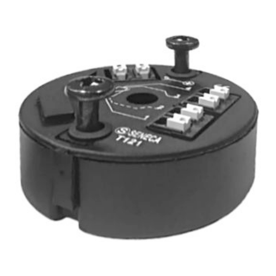
Two-wire universal, isolated transmitter
for RTD sensors and thermocouples
EN
EN
SENECA s.r.l.
Via Austria, 26 – 35127 – PADOVA – ITALY
Tel. +39.049.8705355 - 8705359 - Fax +39.049.8706287
Manuals and configuration software are available at website: www.seneca.it/products/t121
This document is property of SENECA Srl. Duplication and reproduction are forbidden, if not authorized.
Contents of the present documentation refers to products and technologies described in it.
This informations may be modified or integrated for technical and / or commercial requirements.
MI001963-E
ENGLISH - 1/8
THE ORIGINAL IS IN ITALIAN
Advertisement
Table of Contents

Summary of Contents for Seneca T121
- Page 1 Tel. +39.049.8705355 - 8705359 - Fax +39.049.8706287 Manuals and configuration software are available at website: www.seneca.it/products/t121 This document is property of SENECA Srl. Duplication and reproduction are forbidden, if not authorized. Contents of the present documentation refers to products and technologies described in it.
- Page 2 GENERAL DESCRIPTION The T121 instrument converts input signals and retransmits them into a normalized current signal for 4 - 20 mA loop. The input signals may come from J, K, R, S, T, B, E, N thermocouples (EN 60584), RTD sensors (thermistors) as Pt100 (EN 60751), Ni100 (DIN 43760), Pt500, Pt1000 and moreover, the instrument T121 can acquire voltage and resistance values.
- Page 3 TECHNICAL SPECIFICATIONS mV INPUT Input impedance 10 MΩ RTD / RESISTOR INPUT Energizing current μ Sensor fault detection Yes, may be disabled Maximum cable resistance 25 Ω Influence of cable resistance 0.0033 Ω/Ω OTHER FEATURES Sampling time 300 ms Response time (10 – 90%) <...
- Page 4 The module may only be used by qualified and skilled technicians in the field of electric installation. Specific documentation is available for download at website: www.seneca.it/products/t121. Only the Manufacturer is authorized to repair the module or to replace damaged parts.
- Page 5 The module allows to read temperature inputs as TC thermocouples, RTD thermistors with 2, 3 or 4 wire connection and retransmits the input reading value on the 4 - 20 mA output loop. In addition T121 can be used to read voltages (mV) and resistors (Ω). 2 wire RTD...
- Page 6 EASY-USB: USB - UART TTL non insulated converter. The module can be powered from the programming connector. Then you can configure the T121 even if disconnected from the 4 - 20 mA loop. You can set the following parameters: Start and full measurement scale.
- Page 7 2 Move the plastic cover connector as shown in the picture aside. 2 CONNECTIONS TO THE PROGRAMMING CONVERTER S117P1 S117P1 CU-USBA-MINIB-5P T121 CS-RJ10-AMP 2 CONNECTIONS TO THE PROGRAMMING CONVERTER EASY-USB EASY-USB T121 CS-RJ10-AMP FACTORY SETTINGS 2 DEFAULT CONDITION FOR THE CONFIGURATION PARAMETERS...
- Page 8 0 – 1760 Ω CUSTOMIZATION OF THE INTERPOLATION CURVE The EASY SETUP software allows the configuration of the T121 module in order to linearise also the sensors included in the above table (Custom) if their operating range is within the indicated limits.


Need help?
Do you have a question about the T121 and is the answer not in the manual?
Questions and answers