
Related Manuals for DSE DSE890

Summary of Contents for DSE DSE890
- Page 1 DEEP SEA ELECTRONICS PLC ® DSE890 and DSE891 WebNet Gateway Manual Document Number: 057-165 Author: Anthony Manton Page 1 of 53 057-165 ISSUE: 9.0...
- Page 2 DSE890 and DSE891 Webnet Gateway Manual Deep Sea Electronics Plc Highfield House Hunmanby North Yorkshire YO14 0PH ENGLAND Sales Tel: +44 (0) 1723 890099 Sales Fax: +44 (0) 1723 893303 E-mail: sales@deepseaplc.com Website: www.deepseaplc.com ® DSE890 and DSE891 WebNet® Gateway Manual ©...
- Page 3 Added DSE7310 MKII and DSE7320 MKII products to the compatibility table. Added DSE8610 MKII to the compatibility table. Added UL rating. Revised Adding Controller to the DSE Gateway Description. Removed Device compatability table. Revised/simplified Bootloader and Firmware upgrade procedure. Amended user connections - terminals one and two wrong way round.
-
Page 4: Table Of Contents
CONNECTOR B – RS485 ....................14 3.1.2 3.1.3 GSM & GPS CONNECTIONS (DSE890 3G GATEWAY ONLY) ........14 SIM CARD HOLDER (DSE890 3G GATEWAY ONLY) ............15 3.2.1 HOW TO INSERT THE 3G (OR 2G) GPRS SIM CARD ..........15 TYPICAL WIRING DIAGRAM .................... - Page 5 DSE890 and DSE891 Webnet Gateway Manual 5.3.4 LOCATION ........................31 5.3.5 I/O ............................ 31 5.3.6 MODBUS ......................... 31 5.3.7 DATA USAGE ......................... 32 CONFIGURATION ......................... 33 5.4.1 INFO ..........................33 5.4.2 NETWORK ........................34 5.4.3 GSM (DSE890 GATEWAY ONLY).................. 35 5.4.4...
-
Page 6: Introduction
® Where DSE890 3G Gateway is used in conjunction with an appropriate SIM card, the DSEWebNet server can be configured to use the DSE890 Gateway to send SMS messages. This feature is not available when using DSE891 Ethernet Gateway. ®... -
Page 7: Bibliography
Introduction 1.1 BIBLIOGRAPHY This document refers to and is referred to by the following DSE publications which is obtained from the DSE website www.deepseaplc.com Dse Part Description 053-140 DSE890 and DSE891 Installation Instructions ® 057-168 DSEWebNet Software Manual 057-156 DSE334 Configuration Suite PC Software Manual... -
Page 8: Specifications
Specifications 2 SPECIFICATIONS 2.1 TEMPERATURE 2.1.1 OPERATING TEMPERATURE -30 C (-22 F) Minimum Temperature UL enviroment rating = +50 C (122 F) Maximum Temperature None UL environment rating = +60 C (140 F) 2.1.2 STORAGE TEMPERATURE -40 C (-40 F) Minimum Temperature +80 C (176 F) Maximum Temperature... -
Page 9: Terminal Specification
NOTE: GSM / GPRS service is not available with DSE891 Ethernet Gateway. Provided to allow the DSE890 3G Gateway to be connected to a GPRS (internet over GSM) network. 3G or 2G SIM cards are supported. (Optional for use with GPRS support). -
Page 10: Gps Connector
NOTE: DSE stock a Combined GSM/GPS antenna suitable for this purpose. Part number 020-150. DSE testing has shown that separate GSM and GPS antennae tend to give better results than a combined antenna where a clear view of the sky is not available. -
Page 11: Usb Host Connector
Specifications 2.8 USB HOST CONNECTOR This USB type A socket provides support for connection to one DSE controller. Use USB type A to USB type B cable. NOTE: DSE stock a USB suitable cable for this purpose. Part number 016-125. -
Page 12: Rs485 Connector
Specifications 2.10 RS485 CONNECTOR This socket provides support for connection to a maximum of 5 (five) DSE controllers in a daisy chain RS485 network. Ensure termination resistors (120 ) are fitted as shown to the ends of the link as per RS485 standard. -
Page 13: Dimensions And Mounting
Specifications 2.12 DIMENSIONS AND MOUNTING Overall Size 85 mm x 149 mm x 51 mm (3.35” x 5.85” x 2.01”) Weight 120 g (4.23 oz.) Mounting Type DIN rail or chassis mounting DIN Rail Type EN 50022 35 mm type only Mounting Holes M4 clearance Mounting Hole Centres... -
Page 14: Installation
Function Recommended Size RS485 A 0.5 mm² (AWG20) RS485 B 0.5 mm² (AWG20) RS485 Screen 3.1.3 GSM & GPS CONNECTIONS (DSE890 3G GATEWAY ONLY) Connector DSE890 Socket Type Required Antenna Cable Connector Designation SMA FEMALE SMA MALE (Outside thread, female central receptacle) -
Page 15: Sim Card Holder (Dse890 3G Gateway Only)
Installation 3.2 SIM CARD HOLDER (DSE890 3G GATEWAY ONLY) 3.2.1 HOW TO INSERT THE 3G (OR 2G) GPRS SIM CARD Pull back the upper Open the SIM card Slide in the SIM card, Close the cover, ensuring the “edge cover, it clicks as it... -
Page 16: Typical Wiring Diagram
Installation 3.3 TYPICAL WIRING DIAGRAM 3.4 SYSTEM OVERVIEW DSEWEBNET SERVER CONTROLLER(S) Connection to DSE Connection to DSEWebNet Controller(s) Server • • Ethernet • • GPRS RS232 (DSE890 only) • RS485 • Ethernet 057-165 ISSUE: 9.0 Page 16 of 53... -
Page 17: Typical Connection To Dse Controllers
Installation 3.5 TYPICAL CONNECTION TO DSE CONTROLLERS This section shows how to connect DSE controllers to the gateway device. For details on how to connect the gateway to the server, see section entitled Typical connections to gateway server. ® 3.5.1 ADDING THE CONTROLLER TO THE DSE GATEWAY ®... -
Page 18: Device Compatibility
Installation 3.5.2 DEVICE COMPATIBILITY For up to date information regarding device compatibility contact DSE technical support: Tel: +44 1723 890099 Fax: +44 1723 893303 Email: support@deepseaplc.com Web: https://www.deepseaplc.com/support 057-165 ISSUE: 9.0 Page 18 of 53... -
Page 19: Usb (Single Controller)
3.5.3 USB (SINGLE CONTROLLER) USB connection utilises a standard USB A – USB B cable. NOTE: DSE Stock a 2m (2yds) USB Cable DSE Part No 016-125. Alternatively they can be purchased from any PC or IT store. USB cable 3.5.4 RS232 (SINGLE CONTROLLER) -
Page 20: Rs485 (Single Controller)
RS485 connection utilises twisted pair RS485 cable with 120 termination esistors as per RS485 standard. NOTE: DSE stock and supply Belden cable 9841 which is a high quality 120 impedance cable suitable for RS485 use (DSE part number 016-030) 057-165 ISSUE: 9.0... -
Page 21: Ethernet (Single Controller)
Installation 3.5.7 ETHERNET (SINGLE CONTROLLER) Ethernet connection utilises a standard Ethernet cable with RJ45 connectors. Network cable 3.5.8 ETHERNET (MULTIPLE CONTROLLER) Ethernet connection utilises a standard Ethernet cable with RJ45 connectors. Internet or Ethernet router/switch/hub Page 21 of 53 057-165 ISSUE: 9.0... -
Page 22: Typical Connection To Dsewebnet® Server
This is particularly important with wired connection to the internet however usually GSM networks do not include a network firewall. The DSE Server names and port numbers are listed below: Domain name Port www.dsewebnet.com... -
Page 23: Via Ethernet
3.6.4 VIA GPRS (DSE890 3G GATEWAY ONLY) NOTE: GSM / GPRS service is not available with DSE891 Ethernet Gateway. A 2G or 3G GSM SIM card can be fitted into the DSE890. This provides GRPS connection to the DSEWebNet® Server. -
Page 24: Controls And Indications
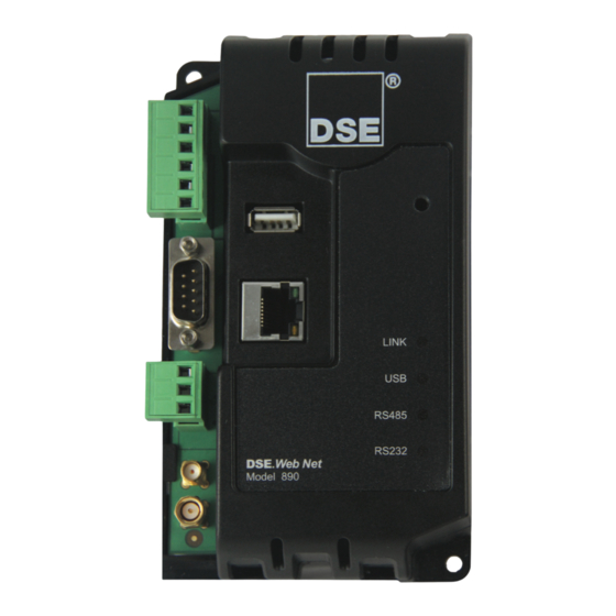
Controls and Indications 4 CONTROLS AND INDICATIONS 4.1 RESET PUSHBUTTON The reset push button, accessible by removing the front cover or via the small hole and by using an insulated narrow point, is provided to set the device back to factory settings. Reset Push Button Access Hole LED1 LINK (Server) Status... -
Page 25: Setup
Setup 5 SETUP is setup using a PC with web browser and a ‘straight through’ or ‘crossover’ ® The DSEGateway network cable. 5.1 BROWSER COMPATIBILITY 5.1.1 GOOGLE CHROME ® The DSEGateway management pages are optimised for Google Chrome web browser. 5.1.2 INTERNET EXPLORER Internet Explorer 10 and above ®... -
Page 26: Connecting To The Gateway Management
Using Google Chrome, Microsoft Internet Explorer or Mozilla Firefox, enter the IP address of the gateway. Enter the username and password of the Gateway : NOTE: Password is CASE SENSITIVE. For further details refer to the following DSE publications available from our website : www.deepseaplc.com ®... -
Page 27: Status
Setup 5.3 STATUS The Status pages show information that can be used for diagnostics and give a level of confidence ® that the system is working as expected. Along with DSEGateway physical information, the displays also indicate the state of the various communication ports in use. The information is separated into subtabs: ®... - Page 28 Setup 5.3.2 NETWORK ® Shows the current network settings in use on the DSEGateway and a status of the connection to the ® DSEWebNet Services. Click Advanced to open and close a diagnostic window to help troubleshoot network connection issues. Parameter Description ®...
- Page 29 Setup 5.3.2.1 ADVANCED The advanced section shows diagnostic information that may assist DSE Technical Support in the case of GSM connection issues. Example showing a successful connection to a Network: ® For details of required firewall settings to allow connection to the DSEWebNet server, see the section entitled Typical Connection to DSEWebNet Server elsewhere in this document.
- Page 30 No green bars indicates poor reception. Move the antenna to a better location. 5.3.3.1 ADVANCED The advanced section shows diagnostic information that may assist DSE Technical Support in the case of GSM connection issues. Example showing a successful connection to a GSM Network, resulting in an IP address being assigned to allow connection.
-
Page 31: Location
Setup 5.3.4 LOCATION ® Shows the current location of the DSEGateway For DSE890, this is either a fixed or GPS devised location, depending upon configuration. For DSE891 this is a fixed (user configured) location. 5.3.5 I/O ® Shows the state of the DSEGateway I/O (Inputs/Outputs). -
Page 32: Data Usage
Setup 5.3.7 DATA USAGE ® ® Shows the amount of data sent by the DSEGateway to the DSEWebNet server. This is useful when determining if the correct package has been purchased from the SIM Card or internet provider. Click to reset the count of data sent to the Click to reset the count of data sent to historic.dsewebnet.co.uk server. -
Page 33: Configuration
Setup 5.4 CONFIGURATION DSEGateway configuration is separated into separate pages. ® NOTE: Upon changing a parameter on any of the pages, the Apply button must be pressed before exiting the current page. This stores the new settings and allows settings on other pages to be changed. A new button, Save Config becomes available after Apply is clicked. -
Page 34: Network
IP address of the Domain Name Service. Usually this is the same as the Gateway IP. ® Host Name Hostname of the device. Used to identify the DSE Gateway on the network. Give this a meaningful name to assist the network IT manager to recognise the device on the network. -
Page 35: Gsm (Dse890 Gateway Only)
Setup 5.4.3 GSM (DSE890 GATEWAY ONLY) ® NOTE: GSM configuration is not available with DSE891 Ethernet Gateway Parameter Description Use GSM Selection for connection to DSEWebNet® Server: = GSM (GPRS) over 2G or 3G network depending upon installation of a suitable SIM card. -
Page 36: Location
World map in the DSEWebNet server. Additionally this location is used for the ® (DSE890 Ethernet Geofence function, to alert users when the DSE890 Ethernet Gateway moves Gateway® only) outside the configured Geofence. If no GPS signal is located, the manually entered location is used. -
Page 37: I/O
Setup 5.4.5 I/O ® Allows configuration of the DSEGateway I/O (Inputs/Outputs) Parameter Description ® Name Enter the name that to identify the I/O channel on the DSEWebNet system. Select the type of the I/O In: The selected channel is an Input. Connect it’s respective terminal to battery ®... -
Page 38: File System
® File System contains templates instructing the ® DSEGateway how to communicate with connected DSE controllers. Initially, ® this file system is empty. The DSEGateway downloads templates as required depending upon which controllers are connected to it. This operation is automatic. -
Page 39: Bootloader Upgrade
Insert the memory stick into the DSEGateway • ® Reapply the DSE power supply to the DSEGateway • Wait for the four status LEDs to stop cycling, then briefly remain green. The link LED status will remain RED whilst communications ®... -
Page 40: Firmware Upgrade
® Insert the memory stick into the DSEGateway • ® Reapply the DSE power supply to the DSEGateway • Wait for the four status LEDs to stop cycling, then briefly remain green. The link LED status ® will remain RED whilst communications to DSEWebnet are restabilished. -
Page 41: Modules Connection
5.5.1 DSEWEBNET ® This page configures how the DSEGateway communicates wih the DSEWebNet® server. NOTE: A maximum of 5 connections can be made in the DSE WebNet page. That is a ® ® maximum of 5 controllers are supported on DSEWebNet by each DSEGateway NOTE: If a Port is used in the Modbus section, it cannot be used to create a DSEWebNet®... - Page 42 Ethernet: Connection to an Ethernet network of one or more controllers. USB: Single connection to a supported DSE controller by USB A – USB B cable. When Port is set to Ethernet – TCP port to use for Modbus (usually 502). Each TCP Port/Baud separate entry must use a unique port number.
- Page 43 = Location of the controller is entered manually. Where multiple controllers Use GPS (DSE890 3G are connected to the DSE890, it may be more appropriate to enter the location Gateway only) of each device manually. This allows each controller to show on the map at its...
-
Page 44: Custom Instruments
Unsigned: The resister is unsigned (register contains positive values only). Size The size of the instrument value (in bits). This must match the bits of the register as documented in the DSE Gencomm protocol document (bits/sign column). 16: The instrument is contained within a single register (16 bits). - Page 45 Example 1: Index: 1 in the screenshot above From the DSE Gencomm protocol document, the following shows the location of the “Oil Temperature” instrument which is read from the CAN ECU of engines that support this feature. This is taken from Page 4 – Basic Instrumentation. Therefore the Page parameter is set to “4”.
- Page 46 Example 2: Index: 2 in the screenshot above From the DSE Gencomm protocol document, the following shows the location of the “Fuel Pressure 1” instrument which is read from the CAN ECU of engines that support this feature. This is taken from Page 5 – Extended Instrumentation. Therefore the Page parameter is set to “5”.
-
Page 47: Modbus
Modbus Gateway to allow conversion across the various ports. It can be used for example to set USB as a modbus master to connect to any DSE controller fitted with a USB port and supporting the DSE Configuration Suite SCADA function. - Page 48 Setup 5.5.3.2 MASTER These are the settings of the DSEGateway® port that is used to connect to the DSE controller. Parameter Description Modbus slave address of the connected DSE controller Port This is the port that is connected to the DSE controller.
-
Page 49: Fault Diagnosis
Port LEDs illuminate RED for a few During the startup sequence, the status LED illuminate seconds at power up of the DSE890. RED. This is normal and if port setup and connections are correct, change to GREEN once communication is underway. - Page 50 Fault Diagnosis Nature of Problem Suggestion Max length of RS485 cable is 1.2km where correct cable and termination resistors are fitted. LED4 – RS232 LED remains RED This means RS232 communications is not successful. Check baud rate and slave ID settings of the ®...
-
Page 51: Maintenance, Spares, Repair, And Servicing
020-150 (DSE890 3G only) 8 WARRANTY DSE provides limited warranty to the equipment purchaser at the point of sale. For full details of any applicable warranty, contact the original equipment supplier (OEM). 9 DISPOSAL 9.1 WEEE (WASTE ELECTRICAL AND ELECTRONIC EQUIPMENT) Electrical and Electronic equipment must be stored, collected, treated, recycled and disposed of separately from other waste. - Page 52 This Page Is Intentionally Blank...
- Page 53 This Page is Intentionally Blank...
Need help?
Do you have a question about the DSE890 and is the answer not in the manual?
Questions and answers