
Related Manuals for DSE DSE892 SNMP

Summary of Contents for DSE DSE892 SNMP
- Page 1 DEEP SEA ELECTRONICS PLC DSE892 SNMP Gateway Manual Document Number : 057-179 Author : Anthony Manton DSE892 SNMP Gateway Manual ISSUE 1...
- Page 2 Sales Fax: +44 (0) 1723 893303 E-mail : sales@deepseaplc.com Website : www.deepseaplc.com DSE892 SNMP Gateway Hardware Manual © Deep Sea Electronics Plc All rights reserved. No part of this publication may be reproduced in any material form (including photocopying or storing in any medium by electronic means or other) without the written permission of the copyright holder except in accordance with the provisions of the Copyright, Designs and Patents Act 1988.
-
Page 3: Table Of Contents
CONNECTOR B – RS485 ..................12 3.13 TYPICAL WIRING DIAGRAM ................... 13 3.14 SYSTEM OVERVIEW......................13 3.15 TYPICAL CONNECTION TO DSE CONTROLLERS ............14 3.15.1 ADDING THE CONTROLLER TO THE DSE892 ............14 3.15.2 DEVICE COMPATIBILITY ..................15 3.15.3 USB (SINGLE CONTROLLER) ................... 16 3.15.4... - Page 4 DSE892 SNMP Gateway Manual 6.3.1 MODULE PAGE ......................33 6.3.1.1 MONITORING EVENTS ..................33 6.3.1.2 MONITORING INSTRUMENTATION ..............34 MODBUS .......................... 35 6.4.1 EXAMPLE OF MODBUS GATEWAY SETTINGS............36 MODULE INSTRUMENTATION ..................37 6.5.1 DETAILED INSTRUMENTATION ................38 FAULT DIAGNOSIS ................... 39 MAINTENANCE, SPARES, REPAIR AND SERVICING ........
-
Page 5: Bibliography
Introduction 1 BIBLIOGRAPHY This document refers to and is referred to by the following DSE publications which can be obtained from the DSE website www.deepseaplc.com DSE Part Description 053-148 DSE892 installation instructions 057-178 DSE43xx Configuration Suite PC Software Manual 057-093... -
Page 6: Snmp
IP networks. It is used to monitor network-attached devices for conditions that warrant administrative attention. An administrative computer (SNMP manager) monitors a group of DSE controllers using a variety of connection methods (detailed elsewhere in this manual). Should an ‘event’ occur, the DSE892 Gateway reports information via SNMP to the manager. -
Page 7: Specifications
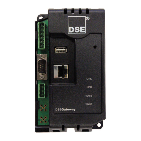
2.5mm² (AWG 14) 3.5 USB HOST CONNECTOR This USB type A socket provides support for connection to one DSE controller. Use USB type A to USB type B cable. NOTE: DSE stock a USB suitable cable for this purpose. Part number 016-125. -
Page 8: Rs232 Connector
Specifications 3.6 RS232 CONNECTOR This socket provides support for connection to one DSE controller. PIN No NOTES Received Line Signal Detector (Data Carrier Detect) Received Data Transmit Data Data Terminal Ready Signal Ground Data Set Ready Request To Send Clear To Send... -
Page 9: Rs485 Connector
Specifications 3.7 RS485 CONNECTOR This socket provides support for connection to a maximum of 16 (sixteen) DSE controllers in a daisy chain RS485 network. Ensure termination resistors (120Ω) are fitted as shown to the ends of the link as per RS485 standard. -
Page 10: Dimensions
Specifications 3.9 DIMENSIONS Overall size 85 mm x 149 mm x 51 mm (3.35” x 5.85” x 2.01”) Weight 120g (4.23 oz.) Mounting type DIN rail or chassis mounting Din rail type EN 50022 35mm type only Mounting holes M4 clearance Mounting hole centres 73 mm x 137 mm (2.89”... -
Page 11: Applicable Standards
Specifications 3.10 APPLICABLE STANDARDS BS 4884-1:1992 This document conforms to BS4884-1 1992 Specification for presentation of essential information. BS 4884-2:1993 This document conforms to BS4884-2 1993 Guide to content BS 4884-3:1993 This document conforms to BS4884-3 1993 Guide to presentation BS EN 60068-2-1 -30°C (-22°F) (Minimum temperature) -
Page 12: Installation
Installation 3.11 INSTALLATION The DSE892 is designed to be mounted within a control panel, either on the panel DIN rail utilising the integral mounts, or chassis mounted, utilising the mounting holes. For dimension and mounting details, see the section entitled Specification, Dimensions elsewhere in this document. 3.12 USER CONNECTIONS 3.12.1 CONNECTOR A –... -
Page 13: Typical Wiring Diagram
Installation 3.13 TYPICAL WIRING DIAGRAM MODEL 0892 3.14 SYSTEM OVERVIEW SNMP MANAGER CONTROLLER(S) Connection to SNMP Connection to DSE manager via ethernet Controller(s) • RS232 • RS485 • Ethernet •... -
Page 14: Typical Connection To Dse Controllers
Installation 3.15 TYPICAL CONNECTION TO DSE CONTROLLERS This section shows how to connect DSE controllers to the gateway device. 3.15.1 ADDING THE CONTROLLER TO THE DSE892 To ensure newly added controllers are recognised by the DSE892, the following steps must be followed. -
Page 15: Device Compatibility
Installation 3.15.2 DEVICE COMPATIBILITY At the time of printing, the following devices are currently compatible with the DSE892. Other devices are being added as part of our ongoing development. NOTE: Not all functions or instrumentation is available with all controllers. Refer to the Configuration Suite PC Software manual relevant to you controller for details of supported events and instrumentation. -
Page 16: Usb (Single Controller)
3.15.3 USB (SINGLE CONTROLLER) USB connection utilises a standard USB A – USB B cable. NOTE: DSE Stock a 2m (2yds) USB Cable DSE Part No 016-125. Alternatively they can be purchased from any good PC or IT store. USB cable 3.15.4 RS232 (SINGLE CONTROLLER) -
Page 17: Rs485 (Single Controller)
Installation 3.15.5 RS485 (SINGLE CONTROLLER) RS485 connection utilises twisted pair RS485 cable with 120Ω termination resistors as per RS485 standard. RS485 cable 3.15.6 RS485 (MULTIPLE CONTROLLER) RS485 connection utilises twisted pair RS485 cable with 120Ω termination resistors as per RS485 standard. -
Page 18: Ethernet (Single Controller)
Installation 3.15.7 ETHERNET (SINGLE CONTROLLER) Ethernet connection utilises a standard Ethernet cable with RJ45 connectors. You must use a multiport network router as the DSE892 requires an Ethernet connection to communicate with the SNMP manager. Internet or Ethernet switch/router 3.15.8 ETHERNET (MULTIPLE CONTROLLER) Ethernet connection utilises a standard Ethernet cable with RJ45 connectors. -
Page 19: Controls And Indications
Controls and Indications 4 CONTROLS AND INDICATIONS 4.1 RESET PUSHBUTTON The reset push button, accessible by removing the front cover or via the small hole and by using an insulated narrow point, is provided to set the device back to factory settings. Reset Push Button access hole Not Used On DSE892 LED2 USB Host Status... - Page 20 Installation...
-
Page 21: Setup
Setup 5 SETUP The DSE892 is setup using a PC with web browser and a ‘straight through’ or ‘crossover’ network cable. 5.1 BROWSER COMPATIBILITY 5.1.1 GOOGLE CHROME The management pages are optimised for Google Chrome web browser. 5.1.2 INTERNET EXPLORER Internet Explorer 9 The management pages are optimised for Internet Explorer 9 Internet Explorer 8... -
Page 22: Connecting To The Gateway Management
Setup 6 CONNECTING TO THE GATEWAY MANAGEMENT PAGES You may wish to consult your company IT department before making changes to your PC network settings. Connect the DSE892 ethernet port directly to your PC Ethernet port. You can use either a ‘straight through’ or ‘crossover’ network cable. -
Page 23: Status
Setup 6.1 STATUS The Status pages show information that can be used for diagnostics and give a level of confidence that the system is working as expected. Along with DSE892 physical information, the displays also indicate the state of the various communication ports in use. -
Page 24: System Settings
Setup 6.2 SYSTEM SETTINGS Ensure you consult with the IT/Network manager of the site that the DSE892 is connected to before making any changes to these settings. 6.2.1 IP Parameter Description DHCP Enabled = The Gateway will request network settings from a DHCP server. = The Gateway’s network settings must be entered manually. -
Page 25: Snmp
Setup 6.2.2 SNMP Ensure you consult with the IT/Network manager of the site that the DSE892 is connected to before making any changes to these settings. Parameter Description IP Address The IPV4 network location of the SNMP manager. Port... -
Page 26: E-Mail
Setup 6.2.3 E-MAIL DSE892 is capable of sending an email to one or two addresses upon detection of an event in the managed devices. Ensure you consult with the IT/Network manager of the site that the DSE892 is connected to before making any changes to these settings. -
Page 27: Time
Setup 6.2.4 TIME Parameter Description Date / Time Set the date and time local to the site. Period am or pm (when 24h Format is not selected) 24h Format = Clock is displayed in 24 hr format = Clock is displayed in 12 hr format Get Time Gets the time from the PC and enters this into the Date and Time boxes above Apply... -
Page 28: File Manager
Setup 6.2.6 FILE MANAGER Parameter Description Download MIB file Creates the DSE892 Gateway’s MIB file. This file is used to configure the SNMP Manager. Download Configuration Creates a backup file of the Gateway’s configuration. Upgrade firmware from See section entitled Firmware Upgrade by TFTP for full description. TFTP Server See section entitled Firmware Upgrade by USB Memory Stick for full Upgrade firmware from... -
Page 29: Firmware Upgrade By Tftp
When available, firmware upgrade files are available by Over The Air updates from Deep Sea Electronics TFTP site. To do this : Ensure your DSE892 SNMP Gateway is correctly configured to access the internet via an • external router. The DHCP is not configured, this requires correct DNS entries in the System Settings | IP section of the DSE892 configuration. -
Page 30: Firmware Upgrade By Usb Memory Stick
When available, firmware upgrade files are available from Deep Sea Electronics PLC website www.deepseaplc.com. To do this you will need : Firmware update filed from DSE. This file must be called 0892-01.bin • • USB flash memory stick formatted to FAT. -
Page 31: Reboot Now
Setup 6.2.6.3 REBOOT NOW Some operations require the gateway to be rebooted (restarted). Examples of this are : Changes to the DSE892 Username or Security Code • Changes to the IP Setup or SNMP Setup • Where this is required, the message Please Reboot to Apply Changes appears under the navigation menu as shown to the left. -
Page 32: Module Setup
Setup 6.3 MODULE SETUP This page is used to configure the DSE892 Gateway’s connections to DSE controllers. Each connected controller has an entry in the table to configure which of the Gateway’s ports are used for connection to that specific module. -
Page 33: Module Page
Description Event For details of supported Events in your connected controller you are referred to the relevant DSE Configuration Suite PC Software Manual. SNMP Trap = This event will not generate an SNMP trap. = Where supported by the connected controller’s event log, the Gateway generates an SNMP TRAP message upon activation of this event. -
Page 34: Monitoring Instrumentation
Modbus Addr The modbus address of the register (instrument) being monitored. For details of available registers you are referred to the DSE Gencomm Document, available upon request from support@deepseaplc.com. The specified registered is read using Modbus Function Code 3 (Read Multiple Holding Registers). -
Page 35: Modbus
Modbus Gateway to allow conversion across the various ports. It can be used for example to set USB as a modbus master to connect to any DSE controller fitted with a USB port and supporting the DSE Configuration Suite SCADA function. -
Page 36: Example Of Modbus Gateway Settings
Index 1 is receiving modbus requests from the external monitoring system on Ethernet, TCP Port 502. ® This is being transferred to the DSE controller via the USB Host port on the DSEGateway Index 2 is receiving modbus requests from the external monitoring system on RS485, baud rate 11500, slave ID 10. -
Page 37: Module Instrumentation
Module Instrumentation 6.5 MODULE INSTRUMENTATION Give status of the configured connections. Each connection also has a detailed instrumentation page (shown overleaf). The name of each page is taken from the name of the connection in the Modbus Passthrough page. -
Page 38: Detailed Instrumentation
Module Instrumentation 6.5.1 DETAILED INSTRUMENTATION NOTE: Only functions supported by the connected controller is shown. For a list of instrumentation and control mode buttons, you are reffered to the relevant controller’s Operator Manual available from www.deepseaplc.com... -
Page 39: Fault Diagnosis
Fault Diagnosis 7 FAULT DIAGNOSIS Nature of Problem Suggestion Factory settings IP Address : 192.168.1.100 Web Management Pages Port : 80 Username : Admin (case sensitive) Password : Password1234 (case sensitive) I’ve forgotton my password and/or IP Press and hold the reset pushbutton. All LEDs illuminate address yellow, then cycle and finally illuminate yellow again. - Page 40 Fault Diagnosis Nature of Problem Suggestion LED3 – USB LED remains RED This means USB communications is not successful. Check settings of the DSE892. Check USB cable is USB A to USB B type cable. Maximum length of USB cable is 6 m unless third party powered USB extender is used.
-
Page 41: Maintenance, Spares, Repair And Servicing
USB A to USB B (DSE892 to host controller) 016-125 8.1 WARRANTY DSE provides limited warranty to the equipment purchaser at the point of sale. For full details of any applicable warranty, you are referred to your original equipment supplier (OEM). 8.2 DISPOSAL 8.2.1 WEEE (WASTE ELECTRICAL AND ELECTRONIC EQUIPMENT) - Page 42 This page is intentionally blank...
Need help?
Do you have a question about the DSE892 SNMP and is the answer not in the manual?
Questions and answers