Table of Contents
Advertisement
Quick Links
02/2014
Manual
_____________________________________________________________________________________________________________________
Mütec Instruments GmbH
Bei den Kämpen 26
D-21220 Seevetal-Ramelsloh
MTP200ia-E, MTP200ib-E
WINSMART-Support from MTP200-Version 4.0
Tel.: +49 (0) 4185-80 83-0
Fax: +49 (0) 4185-80 83-80
MODBUS-RTU Communication
Email:
muetec@muetec.de
Web: www.muetec.de
Advertisement
Table of Contents

Related Manuals for Mutec MTP200ib-E


Summary of Contents for Mutec MTP200ib-E
- Page 1 02/2014 Manual MTP200ia-E, MTP200ib-E WINSMART-Support from MTP200-Version 4.0 MODBUS-RTU Communication _____________________________________________________________________________________________________________________ Mütec Instruments GmbH Tel.: +49 (0) 4185-80 83-0 Email: muetec@muetec.de Bei den Kämpen 26 Fax: +49 (0) 4185-80 83-80 Web: www.muetec.de D-21220 Seevetal-Ramelsloh...
- Page 2 02/2014 Manual for MTP200ia-E, MTP200ib-E WINSMART-Support from MTP200-Version 4.0 MODBUS-RTU communication No.: BA 1.06 Date: 01/2014 Manufacturer: Mütec Instruments GmbH Bei den Kämpen 26 21220 Seevetal Deutschland Tel.: +49 (0) 4185 8083-0 Fax: +49 (0) 4185 808380 E-Mail: info@muetec.de Internet: www.muetec.de...
-
Page 3: Table Of Contents
02/2014 Table of contents Classification of safety instructions ..................... 4 General instructions ........................5 Introduction ..........................6 General information for installation and operation ............7 Electrical maximum values ....................9 Technical Features ......................11 Fault conditions and fault signalling ................12 Technical Data ......................... -
Page 4: Classification Of Safety Instructions
02/2014 Classification of safety instructions This manual contains instructions that you have to observe for your personal safety as well as to avoid material damage. These instructions are highlighted using a triangular warning sign and shown as follows, depending on the degree of risk. HAZARD means that death or severe physical injury will occur if the appropriate precautionary measures are not taken. -
Page 5: General Instructions
02/2014 General instructions This device left the plant in flawless condition in terms of its safety features. To preserve this condition and ensure safe operation of the device, the user has to observe the instructions and warning notes indicated in this operating manual. -
Page 6: Introduction
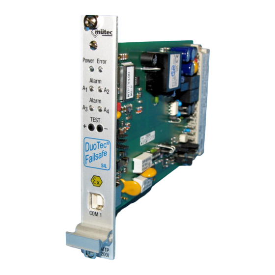
02/2014 Introduction MTP200ia-E, MTP200ib-E Transmitter Supply Unit with SIL2-Level as per IEC/EN 61508 Features: 2 Processors (8- and 16-Bit) with parallel monitoring 4 A/D- converters (24-Bit, 12-Bit, 2x 10-Bit) 1 D/A- converter (15-Bit) 5 Self monitoring circuits ... -
Page 7: General Information For Installation And Operation
02/2014 1. General information for installation and operation Identification in accordance with Guideline 94/9/EG: 0158 II (1) G device group intrinsically safe equipment with external circuits for connection for category 1 devices for explosive mixtures of air and flammable gases, steams or vapours Identification of explosion protection: [Ex ia] IIC... - Page 8 02/2014 The maximum ambient temperature range of -20 °C to +60 °C may not be exceeded. The transmitter MTP200i..-E belongs to equipment of explosion protection (EX ia) IIC or (EX ib) IIC and has to be operated always outside of potentially explosive areas. Only electrical circuits certified as intrinsically safe may be connected to both circuits.
-
Page 9: Electrical Maximum Values
Voltage Current intensity Max. voltage AC/DC Intrinsically safe electric circuits: Pt-100/slide-wire sensor input circuit (contacts d/z28 and d/z30) in the explosion protection EEx ia IIC (MTP200ia-E) or EEx ib IIC (MTP200ib-E) Voltage Current intensity Power Max. outer capacity µF Max. outer inductivity... - Page 10 Effective inside capacity Effective inside inductivity negligible +/-20mA-Input circuit (contacts d24 and d26) in the explosion protection EEx ia IIC (MTP200ia-E) or EEx ib IIC (MTP200ib-E) for the connection of an intrinsically safe circuit with following maximum values: Voltage Current intensity Power...
-
Page 11: Technical Features
02/2014 3. Technical Features The processor-controlled MTP200i..-E universal measuring transducer with limit signal transmitter of the DuoTec® series meets all requirements for temperature, resistance, current and voltage measurement in process automation thanks to its functionality. Reciprocal monitoring of the dual processor system (DuoTec® technology) in combination with further safety measures in accordance with EN 61508 ensures that the unit meets the SIL2 level. -
Page 12: Fault Conditions And Fault Signalling
02/2014 4. Fault conditions and fault signalling Error source Alarm LED Analogue output Alarms Restart after error Remark elimination Error cause in error event (program (programmable) mable) EEPROM: alarm value or --- , MTP200 must be Parameter table in reconfigured, RAM loaded with check sum constant... -
Page 13: Technical Data
02/2014 5. Technical Data ANALOGUE INPUT (AI1 … AI4) A parameterizable filter of first order of (0.1 – 99.9)s! mA-measuring input AE1 Measurement range: -22 ..+22 mA, free configurable 100 Ω Input resistance: V-measuring input AE2 Measurement range: -11 ..+11 V, free configurable Input resistance: 10 kΩ... - Page 14 02/2014 CONTACT OUTPUTS (REL1, REL2), TRANSISTOR OUTPUT (DO1, DO2) Devices with intrinsically safe circuit may be connected over the contact and transistor output with devices with operating voltages under 250V only! Alarm conditions are indicated with yellow front-side LED’s! Number: 4 independently adjustable limit values Setting: physically values with WINSMART-Program...
- Page 15 02/2014 GENERAL DATA Measuring value accuracy Maximum: < 0.04 % from final value Typical: < 0.02 % from final value Temperature coefficient Maximum: < 0.01 %/K Typical: < 0.005 %/K Galvanic separation Input/output/supply: 300 V (rated insulation voltage, overvoltage category II, Contamination level 2, safe separation as per EN 61010, EN 50178);...
- Page 16 02/2014 Mounting The device can only be operated outside a potentially explosive area! 19”-europecard with 4 TE front panel Form of construction: Protection class: IP20 Mounting: for the required protection class the device has to be installed in a rack or in an appropriate housing Mounting/Position free Weight...
-
Page 17: Configuration Protocol
02/2014 5.1. Configuration protocol ® A configuration dated protocol can be created for the MTP200 using the WINSMART program with the command Print configuration. The TAG number, unit-specific device address, serial number and version number are logged as identification in the unit software. The extensive comments saved in the device, with a maximum of 2000 ASCII characters, are printed out in a protocol with the first 60 characters. -
Page 18: Basic Circuit Diagram
02/2014 5.2. Basic Circuit Diagram _____________________________________________________________________________________________________________________... -
Page 19: General View
02/2014 5.3. General view _____________________________________________________________________________________________________________________... -
Page 20: Contacts And Female Multipoint Connector's Coding
02/2014 Contacts and female multipoint connector’s coding 5.4. _____________________________________________________________________________________________________________________... -
Page 21: Jumper-Settings
02/2014 5.5. Jumper-settings Jumper JP1 – JP3: Via Jumper JP3 the analog output is switched from constant current (mA) to voltage (V). At the same time, the Jumper JP1 and JP2 have to be reconnected, thereby it is possible to measure the selected output signal at the test socket in the front. Jumper JP5, JP6, JP7, JP8 and JP9: Measuring input for: JP-5... -
Page 22: Configuration Program
02/2014 6. Configuration program The illustration above shows the opening screen of the WINSMART configuration program for the MTP200 and MTP200 with the corresponding version and release number of the program. The command File in the menu bar is used to access existing configuration files and for saving and printing of the current configuration. -
Page 23: Menu Bar And Commands
02/2014 6.1. Menu bar and commands File Load configuration 6.1.1. The MTP200 parameter set saved in a file with extension *.MTP on the hard drive is loaded into the Windows configuration program. Thus a parameter set already created and saved can be copied fast and reliably into other devices, if the same configuration is needed for these. -
Page 24: Access Rights Change Password Password Level 1
02/2014 Access rights Change password Password level 1 6.1.7. No entry with the first assignment of a password! Password level 1 covers all parameter settings of the MTP200 and is only enabled for authorised personnel (e.g. maintenance staff, service technician) to access all configurable settings. The password may have a maximum of 20 alphanumeric characters and is entered and saved in the corresponding fields as in the screen. - Page 25 02/2014 Before beginning of the calibration the parameters from the MTP200 must be read in! May be implemented only for the actualization of the calibration parameters contained in the MTP200! The JP8/JP9 jumpers define the Pt 100 input configuration as a 2-wire, 3-wire or 4-core circuit. For the resistance measurement, too, only one valid set of parameters can be stored in the MTP200.
-
Page 26: Calibration Calibrate Input Thermocouple
02/2014 Calibration Calibrate input Thermocouple 6.1.10. The set of parameters from the MTP200 has to be read in before beginning the calibration. For calibration of the thermocouple measurement input place the jumpers according to the specifications in the WINSMART mask for activation of the thermocouple measurement input (see section 10.4 Measurement inputs). -
Page 27: Calibration Calibrate Input Resistance, Current And Voltage
02/2014 TRJ-value in the online-mask Example 2: 24.10 °C Measured cold junction temperature 25.00 °C -------------------------------- ΔT = (24,1 - 25,0) °C -0.90 °C Load resistance = 0.39 Ω/°C x (-0.9) °C Ω -0.35 The TRJ calibration has to be carried out while using an external and an internal Pt 100 sensor. -
Page 28: Calibration Calibrate Output Current Or Voltage
02/2014 Calibration Calibrate output Current or voltage 6.1.12. Coarse adjustment by shifting the buttons! Exact adjustment by clicking these surfaces! Final attitude by clicking these Buttons! Before beginning each calibration, the parameter set must be read from the MTP200. A 4½-place digital circuit analyser is connected to the MTP200 output terminals and the output signal is adjusted with the jumper 3 for constant current or voltage. -
Page 29: Language English, German, Dutch
02/2014 Language English, German, Dutch 6.1.14. There are three language versions in the WINSMART program selectable. 6.2. Interface and connected devices Communication between the MTP 200 and the Windows PC is made by the front-side COM/RS232 or RS485 interface at the contacts of mounting rail bus connector. -
Page 30: Mtp-Address
02/2014 6.2.5. MTP-address The MTP address setting regulates communication over the interface with the receiver. The PC, as the master device, sends a transmission with the device address that is read with each MTP200 (slave) by using the COM interface in case of an individual compound or using the RS485 interface in case of a multidrop connection. Only the MTP device with the set address communicates to the master. -
Page 31: Measuring Input
02/2014 6.4. Measuring input All available sensor types and measuring signals for selection and parameterization are listed in the mask of measurement inputs. Of the four different measurement inputs at the terminals of the MTP200, only one can be activated and parameterized in each case. After the sensor type or measured variable has been specified, a window appears with the information for the: Maximum available measuring range Jumpers to be opened/closed... - Page 32 02/2014 For standardized measurement signals further entries must be made in rubric Physical representation of measure value. They are needed for a representation in the online mask. Unit: Physical unit of measured variable (bar, °C, K, etc.) Decimal point: None, 1, 2 or 3 places after the decimal point Start of range: Physical measure value at start of range End of range:...
-
Page 33: Analogue Output
02/2014 6.5. Analogue output The Filter time of minimum 0.1 seconds up to maximum 9.9 seconds defines a first order filter for the output signal. The analogue value is more strongly dampened with increasing filter time. For analogue output the illustration range is set by the definition of values for Start of range and End of Range. -
Page 34: Alarm Outputs
02/2014 6.6. Alarm outputs The mask for the alarm outputs enables quick setting of all parameters due to the clear display of the three alarms available (2x relay contact output, 1x transistor output). A value between 0 and 99.9% of the measuring range is assigned to each alarm value hysteresis. For a measuring range of 500°C a temperature level hysteresis of 2% corresponding to 10°C, with an activated MAX alarm of up to 400°C is only reverse with a temperature level of <... -
Page 35: Differentiated Gradient Alarm And The Parameter Settings
02/2014 6.6.1. Differentiated gradient alarm and the parameter settings 1. Example: Alarm value = 40 °C Alarm type = Gradient-MAX + MIN-alarm Time interval = 60 s (20 samples in 60s) Temp (°C) Start Time (s) MAX-alarm MIN-alarm Every time interval contains 20 samples. The minimum pulse duration at the alarm output is 0.05 x 60 s = 3 s! 2. -
Page 36: Monitoring Conditions
02/2014 6.7. Monitoring conditions A deviation fault between +/- (0.2 - 5.0) % is configured for mA measuring input and analogue output respectively. A tolerance beyond that activates an alarm for maintenance requirement by the relay 3 and a constant light alarm LED on the front of the unit. - Page 37 02/2014 Analogue output in the event of fault: Function Ranking Definition The output signal jumps to the alarm value defined in the alarm value analogue output mask! The output signal remains at the value before fault frozen value occurrence and is in an offline mode! instantaneous The output signal is updated and in online mode, but can value...
- Page 38 02/2014 First example: 1. Fault: measure loop Control of outputs: Alarm value limit lim-prio 2. Fault occurs later: mA-Input Control of outputs: Alarm value The behaviour of the outputs determined by the ranking: Analogue output stays on Alarm value Relay 1 changes from relay off to relay on Relay 2 changes from relay limit to relay on...
-
Page 39: Diagnostic Manager
02/2014 6.8. Diagnostic manager The Diagnostic Manager records all occurred faults clearly inside and outside the MTP200. All 11 monitoring functions are listed in a table and provided with windows for Current fault and Fault memory respectively. Each current fault is signalled as a maintenance alarm by the continuous red lighted alarm LED and relay 3. The diagnostic manager shows the source of these faults in the window current faults and fault memory. -
Page 40: Comment Memory
02/2014 6.9. Comment memory The comment memory offers the user a convenient option of saving comments or notes in the MTP200 device. The allowed capacity for comments is a maximum 2000 ASCII characters and may be sufficiently dimensioned for most applications. For protocols, this text can be printed out with the command Print comment under Windows. -
Page 41: Online Representation
02/2014 6.10. Online representation The online representation shows the input and output signal both analogue and digital. Additional the alarms with their limit values are figured. During exceeded limit value or alarm activation, the value is displayed in red. Unused alarms (no function) are not recorded in the online display. _____________________________________________________________________________________________________________________...
Need help?
Do you have a question about the MTP200ib-E and is the answer not in the manual?
Questions and answers