Table of Contents
Advertisement
Quick Links
Advertisement
Table of Contents

Related Manuals for P.W. KEY rt-208gt


Summary of Contents for P.W. KEY rt-208gt
-
Page 1: Operating Manual
OPERATING MANUAL RT–208GT Room temperature controller Version 5A01... -
Page 2: Table Of Contents
Sensors......................12 Sensors correction..................14 Service password.................... 14 Default settings....................14 Antifreeze program..................14 Technical specification..................15 Schematics of connecting the RT-208GT to the RS-485 data transmission connector......................16 Schematics of connecting the RT-208GT to the RK-2006LPG/LPG2 boiler controller......................17... -
Page 3: Introduction
Application. The RT-208GT controller is a high quality microprocessor device designed for controlling the room temperature. The controller continuously makes measurements both of the room temperature, outside temperature and the boiler temperature and shows the values directly on the display. -
Page 4: Description Of The Rt-208Gt Controller
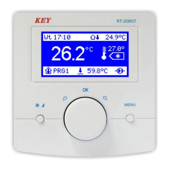
10 - boiler temperature 11 - pump work indicator Function buttons. 12 - mode of work change and change confirmation button 13 - multifunction knob and change confirmation button 14 - MENU/exit button Picture 1. Front cover of the RT-208GT controller. -
Page 5: Description Of Display Symbols
Description of the display symbols. 1,2. Day of the week and an hour. When in the regular mode of work, the current day of the week and time are displayed by the controller. 3. Outside temperature sensor. 4. Outside temperature. When the outside temperature sensor is connected to the controller, the indicator will keep the user informed about the temperature outside the building. -
Page 6: Summary Of The Rt-208Gt Operation
Summary of the RT-208GT operation. The device has been designed for room temperature control and when its value will be lower than the programmed one, the controller will activate the boiler, and the pump work symbol will be shown next to the boiler temperature on the display. Once the temperature programmed for the room is reached, the pump work symbol will be off, the controller will turn off the boiler and switch into the standby mode. -
Page 7: Operation Of The Rt-208Gt
Operation of the RT-208GT. To make the controller more user-friendly all its functions have been divided into groups. At our disposal there are user's and service settings. To make changes in these groups, one should enter the user's menu (press the MENU or OK button once) or the service mode (press and hold for about 5 sec. -
Page 8: Program Edition (Prg 1, Prg 2, Prg 3, Manual Control Program)
3. Program edition (PRG1, PRG2, PRG3, manual program). Within the group of parameters three different week time scheduled programs can be defined according to the user's own needs. Pressing the knob when editing a group, e.g. "Program 1 edition" will result in displaying all the parameters of the group that can be changed. -
Page 9: Manual Control Program
Manual program. Selecting the manual program while the group "Program selection" being edited results in stopping the time scheduled control. The controller will switch into the program of the continuous control. In the mode, night and daytime temperatures only are maintained with the week program deactivated. 4. -
Page 10: Display Settings
6. Display settings. Select the "Display settings" function in the menu to conform display to your own needs. Press the knob while the group of the parameters is edited to see – operation lightness – standby brightness – contrast Description of service parameters. Press and hold the MENU button for about 5 sec. -
Page 11: Boiler Alarms
10. Boiler alarms. Select the "Boiler alarms" function in the menu to set the maximum boiler temperature (temperature of overheating) and the minimum one (shortage of fuel temperature). When the boiler water temperature rises above the maximum programmed temperature, the alarm will be turned on - the boiler temperature indicator and the display will start to blink. -
Page 12: Sensors
VT1–VT4 – first CH system. MIX1–MIX4 – second CH system. CAUTION! When the room controller and the boiler driver have been connected with the data transmission connector, the jumper on the room thermostat input of the boiler driver should be removed and the thermostat number should be set in the room controller, e.g. -
Page 13: Sensors Correction
When the T1 sensor works as the outside temperature sensor, the value measured is also shown in the top row of the display and marked with a house with a thermometer outside. When the additional sensor operates as the boiler temperature sensor, its symbol and the value measured are shown in the bottom row of the display. -
Page 14: Service Password
Confirm your settings (press the knob) and press the MENU button to allow the controller resume its regular work. 15. Set a password. The parameter allows the user to set 5-digit access password to the service settings. Once the password has been typed in, the question "Save new password?" will be displayed - press the OK - and the password will be saved. -
Page 15: Antifreeze Program
17. Antifreeze program. The controller has been provided with the function protecting the room from freezing. When the temperature of boiler water lowers to 5 C, the burner will be activated. When the temperature rises above 5 C, the burner will be turned off and the controller will continue to protect a room from freezing When the controller operates under one of the three week programs, press and hold for 3 sec. -
Page 16: Schematics Of Connecting The Rt-208Gt To The Rs-485 Data Transmission Connector
Schematics of connecting the RT-208GT to the RS-485 data transmission connector... -
Page 17: Schematics Of Connecting The Rt-208Gt To The Rk-2006Lpg/Lpg2 Boiler Controller
Schematics of connecting the RT-208GT room controller to the RK-2006LPG/LPG2 boiler driver... -
Page 19: Declaration Of Conformity
DECLARATION OF CONFORMITY Manufacturer: Przedsiębiorstwo Wielobranżowe KEY Zdzisław Kluczek 11-200 Bartoszyce, ul. Bohaterów Warszawy 67 hereby declares that the product: Regulator RK–208GT is in conformity with provisions of the following directives: 2014/35/UE (LDV) of 26.02.2014r. on the harmonization laws of the Member States of the EU relating to equipment Electrical for use within certain limits, voltage, 2014/30/UE (EMC) z dnia 26.02.2016r. - Page 20 Producent: P.W. KEY 11-200 Bartoszyce, ul. Bohaterów Warszawy 67 tel. (89) 763 50 50, fax. (89) 763 50 51 www.pwkey.pl e-mail: pwkey@onet.pl...
Need help?
Do you have a question about the rt-208gt and is the answer not in the manual?
Questions and answers