Advertisement
Quick Links
RHINO Installation Instructions for PSB24-120 Power Supply
READ INSTRUCTIONS BEFORE INSTALLING OR OPERATING THIS DEVICE. KEEP FOR FUTURE REFERENCE.
(2)
24V
5A
Adjust
DC OK
(1)
100-240V~ 2A
50-60HZ
Figure 1
Figure 2
Figure 3
Figure 4
L
N
GND
L
N
L
N
+ –
+ –
L1
L2
L3
N
GND
L
N
L
N
+ –
+ –
Figure 5
P o w e r D e ra tin g C u rv e fo r P S U
110
100
90
80
70
60
50
40
30
20
10
0
-20
-10
0
10
20
-4
14
32
50
68
Figure 6
(3)
(4)
(5)
AutomationDirect P/N
BM-00120 can be used.
L
L
GND/N
GND/N
L
N
L
N
+ –
+ –
L1
L1
L2
L2
L3
L3
GND/N
N
L
N
L
N
+ –
+ –
30
40
50
60
70
80
85
Am b ie n t T e m p e ra tu re (°C)
86
104
122
140
158
176
185
A m b ie n t T e m p e ra tu re (°F)
1. Safety instructions
• Switch main power off and wait 5 minutes before making any connection or
disconnection on the device. Danger of serious injury or property damage!
• To guarantee sufficient convection cooling, please keep a distance of 50 mm [1.97 in]
above and below the device as well as a lateral distance of 20 mm [0.79 in] to other units.
• Please note, that the enclosure of the device can become very hot depending on
the ambient temperature and load of the power supply. Risk of burns!
• Only plug in and unplug connectors when power is turned off!
• Do not introduce any objects into the unit!
• Dangerous voltage present for at least 5 minutes after disconnecting all sources of power.
• To protect against access to live parts the power supply unit (PSU) must be installed
in a protective enclosure.
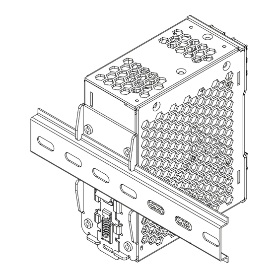
2. Device description (Fig. 1)
(1) Input terminal block connector
(2) Output terminal block connector
(3) DC voltage adjustment potentiometer
(4) DC OK control LED (green)
(5) 35mm DIN rail mounting (DIN rail sold separately)
3. Mounting (Fig. 2)
The power supply unit can be mounted on 35 mm DIN rails in accordance with EN60715.
The device should be installed with input terminal blocks on the bottom.
Each device is delivered ready to install.
Snap on the DIN rail as shown in Fig. 2:
1. Tilt the unit slightly upwards and put it onto the DIN rail.
2. Push downwards until stopped.
3. Press against the bottom front side for locking.
4. Shake the unit slightly to ensure that it is secured.
4. Dismounting (Fig. 3)
To uninstall, pull or slide down the latch as shown in Fig. 3. Then, slide the PSU in the opposite
direction, release the latch and pull out the PSU from the rail.
5. Connection
The terminal block connectors allow easy and fast wiring. A plastic cover provides the necessary
isolation of the electric connection.
You can use flexible (stranded wire) or solid wire with cross section 0.32-2.1 mm² (AWG 22-14)
and torque of 0.78-0.98Nm (6.94-8.68lb in). To secure reliable and shock proof connections, the
stripping length should be 7 mm [0.28 in].
In accordance to EN 60950 / UL 60950, flexible wires require ferrules.
Use appropriate copper wire that is designed to sustain operating temperature of at least 75°C
[167°F] or more to fulfill UL requirements.
For stranded wires it is recommended to use suitable lug (ADC P/N BM-00120) to crimp wires (see
Fig. 4).
5.1. Input connection (Fig. 1, Fig. 5)
Use L, N and GND connections of input terminal connector (see Fig. 1 (1)) to establish the 100-240
VAC connection.
For 3-phase systems just use two phases for the connection to L and N. Need to connect GND and
provide an isolation facility for all poles. The unit is protected with internal fuse (not replaceable)
at L pin and it has been tested and approved on 20A (UL) and 16A (IEC) branch circuits without
L1
L2 (N)
additional protection device. An external protection device is only required if the supplying
branch has an ampacity greater than above. Thus, if an external protective device is necessary, or,
utilized, a minimum value of 20A B- or 13A C- characteristic breaker should be used.
The internal fuse must not be replaced by the user. In case of internal
defect, the unit must be discarded or returned if still under warranty
L1
L2
L3
5.2. Output connection (Fig. 1 (2))
Use the "+" and "-" screw connections to establish the 24 VDC connection. The output provides 24
VDC. The output voltage can be adjusted from 22 to 28 VDC on the potentiometer.
The green LED DC OK displays correct function of the output (Fig. 1 (4)).
The device has a short circuit and overload protection and an overvoltage protection limited to 35
VDC.
5.3. Output characteristic curve
The device functions normal under operating line and load conditions. In the event of a short
circuit or over load the output voltage and current collapses (IO/L or IS/C is > Isurge (150%)). The
secondary voltage is reduced and bounces until short circuit or overload on the secondary side
has been removed.
5.4. Thermal behavior (Fig. 6)
In the case of ambient temperatures above +50°C [122°F], the output capacity has to be reduced
as shown in Figure 6. If the output capacity is not reduced when TAmb > 50°C [122°F] device will
switch into thermal protection mode. The device will cycle output on and off to maintain internal
power dissipation and will recover when ambient temperature is lowered or load is reduced as
far as necessary to keep device in a normal operating mode.
FOR TECHNICAL ASSISTANCE CALL 770-844-4200
Advertisement

Subscribe to Our Youtube Channel
Related Manuals for RHINO PSB24-120


Summary of Contents for RHINO PSB24-120
- Page 1 RHINO Installation Instructions for PSB24-120 Power Supply READ INSTRUCTIONS BEFORE INSTALLING OR OPERATING THIS DEVICE. KEEP FOR FUTURE REFERENCE. 1. Safety instructions • Switch main power off and wait 5 minutes before making any connection or disconnection on the device. Danger of serious injury or property damage! •...
-
Page 2: General Data
Technical Data For PSB24-120 Input (AC) Nominal input voltage 100-240VAC Voltage range 85-264VAC (DC input range 120-375 VDC) Frequency 47-63Hz (0 Hz @ DC input) Nominal current 1.4A @ 115VAC, 0.8A @ 230VAC Inrush current limitation. I2t (+25 °C [77°F]) typ.
Need help?
Do you have a question about the PSB24-120 and is the answer not in the manual?
Questions and answers