Advertisement
Quick Links
Download this manual
See also:
Instruction Manual
Overview
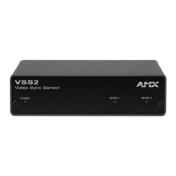
The VSS2 Video Sync Sensor (FG5916-10) is equipped with two independent signal
detection channels. When a signal is present, each detection channel initiates a logic-level
output, and dual video jacks for each channel allow loop-through operation. The VSS2 is an
ideal power sensor for DVDs and other video sources, or to provide a warning on loss of
audio, video or RGB signal.
FIG. 1
VSS2
Common Application
Use the VSS2 to monitor the true power status of a VCR, tuner or satellite receiver and track
the video output of each source, sending a logic signal to an input port.
The output can also be used to control other AMX closure-driven peripherals, such as the
PC1 Power Controller.
Features
•
Detects presence of signal from 1 kHz to greater than 100 kHz
•
2 independent video sync sensing channels
•
2 RCA jacks for each channel to allow loop-through operation
•
2 solid-state outputs that send a logic low signal when sync is present
•
Front-panel LEDs that display on/off status for each channel
•
Compatible with all AMX solid-state and closure input ports
•
Detection of audio, video, and high-resolution RGB signals
Specifications
The following table provides hardware specifications for the VSS2: he table below lists the
specifications for the VSS2 Video Synch Sensor.
Specifications
Power Supply
12 VDC at 20 mA
Power Consumption 2.4 W maximum
Sensitivity
• Video - 800 mV (typical), 5V (max)
• Sync - 15.75 kHz
• Sensing - 1 kHz to 3 MHz (200 mV rms minimum), 3 MHz to 20
MHz (600 mV rms minimum), and 20 MHz to 75 MHz (750 mV
rms minimum)
• RGB Sensing - Sync on Green, Horizontal Sync
• Output - Open collector with internal pull-up to 5 volts and solid-
state logic low when sync is present.
Front Panel
• Power - Green LED indicator
• Sense 1 - Red LED lights when signal is within sensing range
• Sense 2 - Red LED lights when signal is within sensing range
Rear Panel
• Video 1 - RCA jacks for OUT and IN
• Video 2 - RCA jacks for OUT and IN
• Sense Out 1 and 2 - 4-pin Phoenix connector
• 12 VDC-2-pin Phoenix connector
• Delay - None (input connected directly to output)
Enclosure
Metal with black matte finish
Dimensions (HWD)
1.5" x 5.09" x 5.27" (3.81 cm x 12.93 cm x 13.39 cm)
Weight
6.70 oz (189.94 g)
Included
• One 4-pin cable connector
Accessories
• One 2-pin power connector
Optional
• 12 VDC power supply, 20 mA minimum
Accessories
• AC-RK Accessory Rack Kit
VSS2
Applications
Figure 3 shows a sample VSS2 system configuration with a 12 VDC power supply, television
manager, and two video devices (VCRs).
Video Destination 2
12 VDC
Video 2 - IN
Power Spply
Video 2 - OUT
Video Source 2
FIG. 2
Sample VSS2 system configuration
Installation
You can install the VSS2 on any flat surface that has unobstructed access to the rear panel
connectors. The following describes how to set up and install the VSS2.
Connecting the Wiring
You can connect up to two video devices to the RCA plug-in connectors on the VSS2. Once
attached, you can connect up to two external sensing devices, a television manager, or a
AMX control system to the four-pin Sense out connector on the rear panel.
The following sections describe how to connect your video devices, external equipment, and
the 12 VDC power supply
Video 1 and 2 Connectors
FIG. 3 shows how to connect your video devices to the Video 1 and 2 RCA plug-in
connectors on the rear panel.
Video
OUT
IN
Source 1
Video
OUT
IN
Source 2
FIG. 3
Video RCA connector diagram
Sense Out Connector
FIG. 4 shows how to connect two external video-sensing devices.
SENSE2
GND2
Sense out
connector
SENSE1
GND1
FIG. 4
External video sensing wiring diagram
FIG. 5 shows a typical connection of a television manager.
SENSE2
Sense out
GND2
connector
SENSE1
GND1
12 VDC power
GND (-)
supply connector
PWR (+)
FIG. 5
Television manager and power supply wiring diagram
Installation Guide
Video Sync Sensor
Video Destination 1
Video 1 - IN
Television Manager
Video 1 - OUT
Video Source 1
VSS2
Video
Destination
OUT
IN
1
Video
Destination
OUT
IN
2
Sense 2
Sense 1
PWR
I/O 4
Television
I/O 3
manager
I/O 2
I/O 1
GND
Video
1
Video
2
Advertisement

Summary of Contents for AMX VSS2
-
Page 1: Specifications
Common Application connectors. The following describes how to set up and install the VSS2. Use the VSS2 to monitor the true power status of a VCR, tuner or satellite receiver and track Connecting the Wiring the video output of each source, sending a logic signal to an input port. - Page 2 Place the unit in the appropriate opening in the AC-RK. Place the front panel of the VSS2 on the front of the rack, over the unit. Fasten the front panel to the rack and to the unit with the two screws you removed.


