Table of Contents
Advertisement
Quick Links
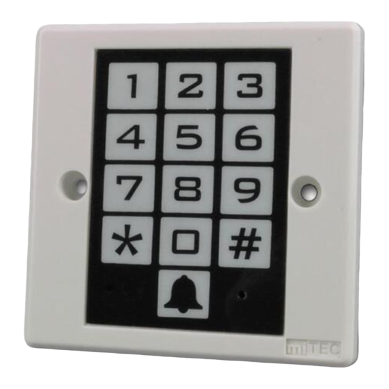
Terminal Description:
Back View:
4
MKP-1211/1221 User Manual
Introduction:
MKP-1320 digital keypad is designed for the
application with electronic locks, entrance
guarding
and
security
systems.
miTECH's latest self-developed IC, data will
not be lost in case of power failure.
Aside from the normal keypad functions,
MKP-1320
also
has
some
functions, such as
door monitoring, alarm
signal output, tamper resistance and door
releasing button input making it a reliable
product.
MKP-1320
provides
a
convenient
automatic way in access management which
is especially suitable for offices, apartments
and commercial buildings.
Power Source Input:
Connecting with AC/DC12V power supply.
Door Releasing Button:
Connecting with a normally opened (N.O.) button to control the Electric Lock Output.
The lock will be released as the button is pressed.
Magnetic Door Sensor (Reed):
Connecting with a normally closed (N.C.) magnetic door sensor (Reed). If the door is
broken in or is opened for a period longer than the setting time, there will be an alarm.
Tamper Button:
A (N.C.) button locating on the rear for resisting tamper. There will be an alarm as it is
activated.
Electric Lock Output:
A transistor output (Max. 24V/2A) with PPTC protection.
Door Bell:
Normally Opened (N.O.) terminals for connecting with a door bell (Max. 24V/100mA)
(Only for MKP-1221)
LED Indicators:
Red:
Power Indicator
Yellow: Program Mode Indicator
Green: Door Indicator
1. Lightened: correct password
2. Flash: opened door
With
additional
and
1
Advertisement
Table of Contents

Subscribe to Our Youtube Channel
Related Manuals for MiTEC MKP-1211


Summary of Contents for MiTEC MKP-1211
- Page 1 MKP-1211/1221 User Manual Terminal Description: Introduction: MKP-1320 digital keypad is designed for the application with electronic locks, entrance guarding security systems. With miTECH's latest self-developed IC, data will not be lost in case of power failure. Aside from the normal keypad functions,...
- Page 2 Wiring Diagram: (1) Connection with a Electric-Lock Power Supply: * For the above connection, the switch S3 should be put to the NO position (2) Connection with a Electric Lock : * For connecting with a fail-secure lock, the switch S3 should be put to the NO position For connecting with a fail-safe lock, the switch S3 should be put to the NC position...
Need help?
Do you have a question about the MKP-1211 and is the answer not in the manual?
Questions and answers