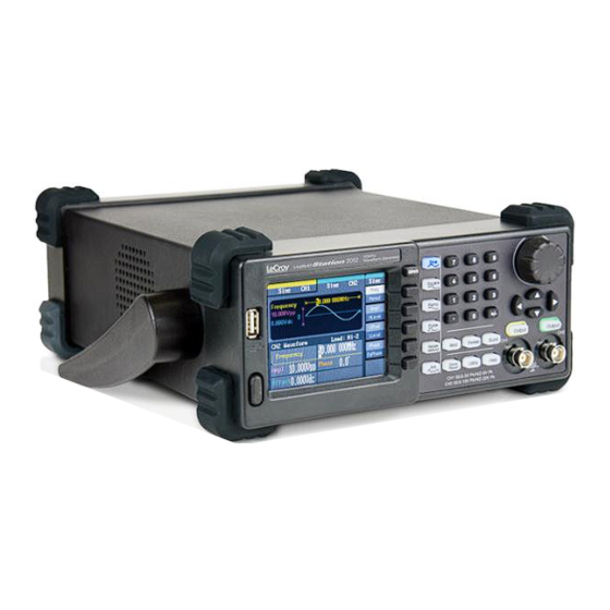
LeCroy WaveStation 2052 Operator's Manual

Function/ arbitrary waveform generator
Table of Contents

Advertisement

Operator's
M anual
WaveStation
Function/ Arbitrary
Waveform Generator

Advertisement

Table of Contents
loading

Summary of Contents for LeCroy WaveStation 2052

  • Page 1 Operator’s M anual WaveStation Function/ Arbitrary Waveform Generator...
  • Page 2 WaveStation Function/Arbitrary Waveform Generator March, 2012...
  • Page 3 LeCroy shall not be responsible for any defect, damage, or failure caused by any of the following: a) attempted repairs or installations by personnel other than LeCroy representatives or b) improper connection to incompatible equipment, or c) for any damage or malfunction caused by the use of non-LeCroy supplies.
  • Page 5: Table Of Contents

    Operator's Manual TABLE OF CONTENTS Welcome ................ 6 Contact LeCroy for Support ........... 6 Thank You ..............7 Package Contents ............8 Safety Requirements ............8 Safety Symbols ............... 8 Operating Environment ..........10 Cooling ................. 11 AC Power Source............11 Power Consumption ............
  • Page 6 WaveStation Creating Waveforms ............. 27 Creating Waveforms Overview ........27 Creating a Sine Wave ........... 28 Frequency/Period............28 Amplitude/HLevel ............29 Offset/LLevel ..............30 Phase/EqPhase ............. 31 Creating a Square Wave ..........31 Duty Cycle ..............32 Creating a Ramp Wave ..........33 Symmetry ..............
  • Page 7 Making the WaveStation - PC Software Connection ... 80 Reference ..............89 Specifications ............... 89 CERTIFICATIONS ............89 CE Declaration of Conformity ........89 China RoHS Compliance ..........91 China RoHS Compliance (English Version) ....92 Contact LeCroy for Support ......... 93 Index ................96 WSta-OM-E RevA...
  • Page 8: Welcome

    When your WaveStation is delivered, verify that all items on the packing list or invoice copy have shipped correctly. Contact your nearest LeCroy customer service center or national distributor if anything is missing or damaged. If you do not contact us immediately, we cannot be responsible for replacement.
  • Page 9: Thank You

    Operator's Manual Thank You We truly hope these materials provide increased comprehension when using LeCroy's fine products. Sincerely, David C. Graef LeCroy Corporation Vice President and Chief Technology Officer WSta-OM-E RevA...
  • Page 10: Package Contents

    WaveStation Package Contents The standard WaveStation package includes the following:  WaveStation Function/Arbitrary Waveform Generator  Power Cord  Standard USB 2.0 Type A to Type B Cable, 1 m  USB to GPIB Converter Cable  WaveStation Operator's Manual ...
  • Page 11 Operator's Manual This symbol is used to denote the measurement ground connection. This symbol is used to denote a frame or chassis connection. This symbol is used to denote a safety ground connection. This symbol is used to denote Power. It is located on the front panel and denotes Power On/Off status of the instrument.
  • Page 12: Operating Environment

    WaveStation CAT I Installation (Overvoltage) Category rating per EN 61010-1 safety standard and is applicable for the instrument front panel measuring terminals. CAT I rated terminals must only be connected to source circuits in which measures are taken to limit transient voltages to an appropriately low level.
  • Page 13: Cooling

    Operator's Manual Cooling The instrument relies on forced air cooling with an internal fan and ventilation openings. Care must be taken to avoid restricting the airflow around the apertures (fan holes) at the side of the instrument. CAUTION Do not allow any foreign matter to enter the instrument through the ventilation holes, etc.
  • Page 14: Hardware And I/O

    WaveStation If you suspect the instrument's protection has been impaired, disconnect the power cord and secure the instrument against any unintended operation. The instrument's protection is likely to be impaired if, for example, the instrument shows visible damage or has been subjected to severe transport stresses.
  • Page 15: Front Panel

    Operator's Manual You can also move the handle into a tucked position under the generator for different viewing positions. Front Panel Numbered callouts on this image correspond with the following descriptions. 1. Power Button 2. USB Connector - USB 2.0 connector which is used for making USB- GPIB or Memory Stick connections as explained in Controlling WaveStation with USB-GPIB and/or USBTMC (on page 76) and Main Save/Recall Operations (on page 57), respectively.
  • Page 16: Back Panel

    WaveStation Specifically, the top three buttons are Waveform Signal Conditioning buttons and apply Mod, Sweep, or Burst functions to the waveform you've selected. Meanwhile, the lower three, Save/Recall, Utility, and Help, are for various WaveStation tools and configurations along with some Help information. 8.
  • Page 17: Getting Started With Wavestation

    Operator's Manual 2. USB Connector - USB 2.0 connector which is used for making USBRAW or USBTMC connections as explained in WaveStation PC Software Overview (on page 78) and Controlling WaveStation with USB-GPIB and/or USBTMC (on page 76), respectively. 3. Ground Connector 4.
  • Page 18 WaveStation Waveform types include Sine, Square, Ramp, Pulse, Noise, and Arb. When using the Function buttons, shows the selected function from Modulate, Sweep, Burst, Save/Recall, Utility, and Help. 5. Operation Menu - This menu changes based on the selected Waveform or Function chosen. Refer to more detailed corresponding coverage later in this manual for more information.
  • Page 19 Operator's Manual 2. At this point, the Display Menu Operation buttons are used to select applicable parameters and make adjustments as desired. The operation menu's currently selected parameter is shown in white. While navigating, you'll come across the following interfaces and button type combinations.
  • Page 20 WaveStation  Parameter Label and Selection Display Button - However, some parameters look like they're first/second press shared buttons, and really are not. Instead, the parameter title is shown in the top portion and the lower portion displays the particular parameter selection as the following Shape parameter shows.
  • Page 21 Operator's Manual Controls (on page 27), and then pressing the same corresponding operation menu button again to preserve the adjustment/selection. The only variation includes where the interface shows the adjustment/selection choices.  Inside the Operation Menu - Some adjustment/selection choices are shown right on the Operation menu. ...
  • Page 22 WaveStation  On the Detail Dialog - Some adjustment/selection choices are shown right on the Detail dialog.  On the Browser Display Dialog - Some interfaces are provided using file explorer-like screens for saving and recalling a variety of folders and file types. WSta-OM-E RevA...
  • Page 23: Waveform Types And Default Parameters

    1. Sine - The default Sine waveform is set to 1 kHz frequency, 4.0 Vpp amplitude and a 0V dc offset. The WaveStation can produce 1 μHz up to 50 MHz (WaveStation 2052) Sine waves. 2. Square - The default Square waveform is set to 1 kHz frequency, 4.0 Vpp amplitude, 0V dc offset with a 50% duty cycle.
  • Page 24: Initial Function Settings

    WaveStation Initial Function Settings Each function (Modulate, Sweep, Burst, Save/Recall, Utility, and Help) contains default settings when initially selected. Specifically, the top three buttons are Waveform Signal Conditioning buttons and apply Mod, Sweep, or Burst functions to the waveform you've selected. Meanwhile, the lower three, Save/Recall, Utility, and Help, are for various WaveStation tools and configurations along with some Help information.
  • Page 25: Save/Recall, Utility, And Help Buttons

    Operator's Manual  Burst - Press the Burst button and the waveforms you've created using the WaveStation are generated for either N-Cycle Burst (a specified number of waveform cycles) or Gated Burst (controlled by an external gated signal). Note: Sine, Square, Ramp, or Arb waveforms may be set to an N-Cycle Burst, while Noise is the only waveform type available for a Gated Burst.
  • Page 26: Save/Recall, Utility, And Help Function Buttons

    WaveStation Menus are therefore displayed in a prioritized order of Waveform Type (one of which is always selected) and a second level of Mod, Sweep, or Burst (one of the three at a time). However, it is not mandatory to apply Mod, Sweep, or Burst functionality to your selected waveform.
  • Page 27 Operator's Manual So, at any given time, you can press the Save/Recall, Utility, or Help function button, and the corresponding menu is shown. Similar to Mod, Sweep, or Burst these buttons are optional and a second press turns off their corresponding LED and function to reveal either the the Mod, Sweep, or Burst menu if applied to the selected waveform, otherwise, the selected waveform type menu is shown.
  • Page 28 WaveStation WSta-OM-E RevA...
  • Page 29: Digital Input Front Panel Controls

    Operator's Manual Digital Input Front Panel Controls Three sets of buttons - The Number Buttons, The Direction Buttons, and the Adjustment Control Knob - all provide unique means to provide digital input from the Front Panel (on page 13) in the following ways: 1.
  • Page 30: Creating A Sine Wave

    WaveStation This section covers details around creating waveforms and making specific adjustment/selection parameter choices - all of which vary based on the specific waveform selection made. For more information on getting to this point, see Navigating Interfaces, Adjusting Parameters, and Making Selections (on page 16). Creating a Sine Wave When first pressing this waveform button on the Front...
  • Page 31: Amplitude/Hlevel

    Operator's Manual PLEASE NOTE THE FOLLOWING:  Press the Frequency/Period operation button a second time to select and adjust the Period parameter in the same manner.  While editing certain parameters using the Number Buttons, applicable unit(s) are shown on the Operation menu. Press an adjacent Operation button to select a desired Unit for your entry.
  • Page 32: Offset/Llevel

    WaveStation  Press the Amplitude/HLevel operation button a second time to select and adjust the HLevel (High Level) parameter in the same manner. Second operation button press parameters are shown in reverse color on the waveform detail dialog to provide a visual indication as to which parameter is being adjusted.
  • Page 33: Phase/Eqphase

    Operator's Manual  Provide your desired Offset or LLevel using the Digital Input Front Panel Controls (on page 27). Phase/EqPhase With the Sine waveform and the Phase/EqPhase operation button pressed once to select Frequency, a Sine waveform is shown on the Waveform Display and the Phase is shown on the Waveform Detail dialog.
  • Page 34: Duty Cycle

    WaveStation Press adjacent Operation buttons and use the Digital Input Front Panel Controls (on page 27) to make specific adjustment/selection parameter choices. For more information on getting to this point, see Navigating Interfaces, Adjusting Parameters, and Making Selections (on page 16). Note: Square Operation menu selections and parameters include Frequency/Period, Amplitude/HLevel, Offset/LLevel, Phase, and Duty Cycle.
  • Page 35: Creating A Ramp Wave

    Operator's Manual % of High Level Frequency 20 to 80% < 10 MHz 40 to 60% From 10 MHz to 20 MHz > 20 MHz PLEASE NOTE THE FOLLOWING:  Press an adjacent Operation button to select a desired Unit (unit interval) for your entry.
  • Page 36: Symmetry

    WaveStation Symmetry With the Ramp waveform and the Symmetry operation button pressed, a Ramp waveform is shown on the Waveform Display and Symmetry is shown on the Waveform Detail dialog. PLEASE NOTE THE FOLLOWING:  Press an adjacent Operation button to select a desired Unit (unit interval) for your entry.
  • Page 37: Pulwidth/Duty

    Operator's Manual For more information on getting to this point, see Navigating Interfaces, Adjusting Parameters, and Making Selections (on page 16). Note: Pulse Operation menu selections and parameters include Frequency/Period, Amplitude/HLevel, Offset/LLevel, PulWidth/Duty, and Delay. The parameters for Frequency/Period, Amplitude/HLevel, and Offset/LLevel are carried out the same way as done when Creating a Sine Wave (on page 28).
  • Page 38: Delay

    WaveStation Delay With the Pulse waveform and the Delay operation button pressed once, a Pulse waveform is shown on the Waveform Display and the Delay is shown on the Waveform Detail dialog. PLEASE NOTE THE FOLLOWING:  Press an adjacent Operation button to select a desired Unit (unit interval) for your entry.
  • Page 39: Variance/Mean

    Operator's Manual Set Variance/Mean values on Noise Waveforms as follows: Variance/Mean With the Noise waveform and the Variance/Mean operation button pressed once to select Variance, a Noise waveform is shown on the Waveform Display and Variance is shown on the Waveform Detail dialog.
  • Page 40: Load Wform

    WaveStation Press adjacent Operation buttons and use the Digital Input Front Panel Controls (on page 27) to make specific adjustment/selection parameter choices. For more information on getting to this point, see Navigating Interfaces, Adjusting Parameters, and Making Selections (on page 16). PLEASE NOTE THE FOLLOWING: ...
  • Page 41 Operator's Manual UILT RBITRARY AVEFORMS After selecting Arb → Load Wform → Built-In, a menu is shown categorizing the Built-In Arbitrary Waveforms as follows: Note: After selecting one of the following categories using the adjacent Operation button, the built-in waveforms are shown on the Waveform Display dialog and may be selected using the Digital Input Front Panel Controls (on page 27) - specifically, the Direction Buttons or the Control Knob.
  • Page 42 WaveStation TORED AVEFORMS After selecting Arb → Load Wform → Stored Wforms, the Stored Waveforms are shown on the Waveform Display dialog as follows: Note: Select the stored waveforms showing on the Waveform Display dialog using the Digital Input Front Panel Controls (on page 27) - specifically, the Direction Buttons or the Control Knob.
  • Page 43: Generating Modulated Waveforms

    Operator's Manual Generating Modulated Waveforms Generating Modulated Waveforms Overview Specific waveform types may be modulated (as carrier waveforms) using the WaveStation. Sine, Square, Ramp, or Arb waveforms may be modulated, while Pulse, Noise, and DC cannot. The first step in creating your modulated waveform is to press the Mod Function button on the Front Panel.
  • Page 44 WaveStation Press adjacent Operation buttons and use the Digital Input Front Panel Controls (on page 27) to make specific adjustment/selection parameter choices. For more information on getting to this point, see Navigating Interfaces, Adjusting Parameters, and Making Selections (on page 16). Mod →...
  • Page 45 Operator's Manual Press adjacent Operation buttons and use the Digital Input Front Panel Controls (on page 27) to make specific adjustment/selection parameter choices. For more information on getting to this point, see Navigating Interfaces, Adjusting Parameters, and Making Selections (on page 16). Mod →...
  • Page 46 WaveStation Press adjacent Operation buttons and use the Digital Input Front Panel Controls (on page 27) to make specific adjustment/selection parameter choices. For more information on getting to this point, see Navigating Interfaces, Adjusting Parameters, and Making Selections (on page 16). ASK modulation represents digital data as variations in the amplitude of a carrier wave.
  • Page 47 Operator's Manual Generating an FSK (Frequency Shift Keying Modulation) Modulated Waveform After selecting the Mod → FSK modulated waveform operator button as explained in the Generating Modulated Waveforms Overview (on page 41), the WaveStation shows the FSK Operation menu and corresponding Display and Detail dialogs.
  • Page 48 WaveStation  Hop Freq - Specify the desired hop frequency level (for variation from the set carrier waveform frequency).  Source - Select Internal or External. If External is selected, use the Trig/Gate/Fsk/Burst connector on the Back Panel (on page 14). Generating an PM (Phase Modulation) Modulated Waveform After selecting the Mod →...
  • Page 49: Generating Sweep Waveforms

    Operator's Manual Mod/PM Operation menu selections and parameters include PM Freq, Phase Dev, Type, Shape, and Source as follows:  PM Freq - This parameter sets the frequency at which the output amplitude shifts between the carrier amplitude and 0. The internal source frequency range is 2 MHz to 50 kHz.
  • Page 50 WaveStation This section covers sweep waveform creation and making specific adjustment/selection parameter choices - all of which vary based on the specific function and carrier waveform selection made. While details around creating waveforms and adjusting specific parameters (which vary based on the specific sweep waveform) are covered here, the following section covers some menu control considerations.
  • Page 51 Operator's Manual PLEASE NOTE THE FOLLOWING:  Some parameters look like they're first/second press shared and really are not. Instead the parameter title is shown in the top portion and the lower portion displays the particular parameter selection.  Operation menus containing more parameters than the ones showing on the first menu have a 1/X ↓...
  • Page 52 WaveStation Press adjacent Operation buttons and use the Digital Input Front Panel Controls (on page 27) to make specific adjustment/selection parameter choices. Sweep Operation menu selections and parameters include SwpTime, StopFreq, FreqSpan, StartFreq, MidFreq, Source, TrigOut, Linear/Log, and Direction as follows: ...
  • Page 53: Generating Burst Waveforms

    Operator's Manual  Linear/Log - Press this operation button to highlight and select either Linear or Log spacing for your sweep waveform.  Direction - Press this operation button to toggle between an upward (↑) or downward (↓) sweep direction for your waveform.
  • Page 54 WaveStation Common Burst Waveform Menu Controls and Considerations  After pressing the Burst button on the Front Panel (on page 13), select the desired modulated waveform type using the Display Menu Operation buttons. The waveform is shown on the Waveform Display. ...
  • Page 55 Operator's Manual PLEASE NOTE THE FOLLOWING:  Some parameters look like they're first/second press shared and really are not. Instead the parameter title is shown in the top portion and the lower portion displays the particular parameter selection.  Operation menus containing more parameters than the ones showing on the first menu have a 1/X ↓...
  • Page 56 WaveStation Burst Operation menu selections and parameters include Period, StartPhase, NCycle/Gated, Source, TrigOut, Cycles/Infinite, and Delay as follows:  Period - This control is only available when NCycle is selected from the third operation button. Press the Period operation button and provide a specific value for the Pulse Period control using the detail dialog.
  • Page 57 Operator's Manual  Cycles/Infinite - This control is only available when NCycle is selected from the third operation button. Press this operation button to highlight and select either Cycles or Infinite amounts for your burst waveform(s). With Cycle selected, provide a desired amount of repetitions (from 1 to 50,000) using the detail dialog.
  • Page 58: Save/Recall

    WaveStation Save/Recall Save/Recall Overview The first step when using the Save/Recall is to press the corresponding Save/Recall function button on the Front Panel (on page 13). The following interface is shown with the Store Operation menu on the right side of the screen. PLEASE NOTE THE FOLLOWING: ...
  • Page 59: Main Save/Recall Operations

    Operator's Manual Main Save/Recall Operations After pressing the Save/Recall button on the Front Panel (on page 13), select the desired function using the corresponding Display Menu Operation buttons. Note: Default values for most save/recall parameters may be set using certain options available from the Utility menu. Learn more in Main Utility Operations (on page 62).
  • Page 60: Operation Menu Selections And Parameters

    WaveStation A good portion of the operation buttons control two separate parameters. Operation buttons controlling two parameters have additional, lighter shaded function labels on them; press the button once to adjust the top control parameter; twice to adjust the bottom one. Make adjustments using the Digital Input Front Panel Controls (on page 27).
  • Page 61 Operator's Manual  FileType - This control contains State, Data, and All File options based on which kinds of files are being used. State (or Setup) handles various WaveStation setup files, Data handles arbitrary waveform files, and All File is used when storing or recalling any other file type.
  • Page 62 WaveStation PLEASE NOTE THE FOLLOWING:  If you're saving State (Setup) or Data (Arbitrary Waveforms) onto your WaveStation, onto one of their 10 specific Memory Banks, and select a Bank/File location already containing previously stored information, your new information always overwrites the old. ...
  • Page 63 Operator's Manual o Use the Cancel option button if you wish to return to the main Save/Recall menu without saving your file. Note: Refer to the WaveStation PC Software Overview (on page 78) to learn how to transfer waveform files between the WaveStation and your PC.
  • Page 64: Utility

    WaveStation  External Hard Drives are not supported for use as USB flash memory. The front USB is meant for use by what is commonly known as memory sticks or thumb drive devices. Utility Utility Overview The first step when using Utility is to press the corresponding Utility function button on the Front Panel (on page 13).
  • Page 65: Wsta-Om-E Reva

    Operator's Manual  Second operation button press parameters are shown in reverse color on the waveform detail dialog to provide a visual indication as to which parameter is being adjusted in the detail dialog. PLEASE NOTE THE FOLLOWING:  Some parameters look like they're first/second press shared and really are not.
  • Page 66 WaveStation quickly select a 1/-1V or 2/-2V DC Offset using corresponding option buttons. Note: After pressing either 1/-1V or 2/-2V DC Offset option buttons, the Adjustment Control Knob may also be used to dial in the desired level within a -3 to 3V range. ...
  • Page 67 Operator's Manual  The USB connector on the Front Panel is also used for USB memory sticks. USB memory sticks are plug- and-play supported and no special setting is needed for their use. o Make selections as desired and press the Done (to commit) or Cancel option button and the main Util menu is shown.
  • Page 68 WaveStation  Default - The Sync signal should be connected to the activated Sync Out connector on the Back Panel. When the Sync Signal is disabled, the output voltage of the [Sync] connector is set to low level.  Inverse - In this mode, the Waveform corresponding to the Sync Signal does not inverse.
  • Page 69 Operator's Manual  System - Press this option button on the 2/2 main Util menu and additional menus (there's actually two - shown here side by side for convenience) are provided where you can make various default settings on your WaveStation. Note: The menus don't appear on the WaveStation this way and are provided here side-by-side for convenience.
  • Page 70 WaveStation Otherwise, subsequent presses of corresponding buttons select the available values. Note: When selecting the Set to Default option button, your WaveStation is restored to various factory settings as described in Restoring the Default Settings (on page 73). Make selections as desired and press the Done (to commit) option button and the System menu is shown.
  • Page 71 Operator's Manual Screen, Keyboard, and LED Test screens look like the following: Screen Test - Each press of the 7 front panel button runs successively through colors and is how the Screen Test is performed. Move through a few colors until you are satisfied. As the screen indicates, press the 8 front panel button to exit.
  • Page 72 WaveStation Keyboard Test - As front panel buttons and knobs are pressed and turned, the screen colorizes their corresponding location on the test screen, indicating a successful test. Test all of the instruments buttons and knobs as desired. As the screen indicates, pressing the 8 front panel button three times exits the keyboard test.
  • Page 73 Operator's Manual LED Test - Each press of the 7 front panel button illuminates successively from the Waveform Type buttons, to the Waveform Signal Conditioning buttons, to the Save/Recall, Utility, and Help buttons, to the two Output buttons (since these are the only LED buttons on the Front Panel).
  • Page 74  Update - Firmware updates are made available for the WaveStation function/arbitrary waveform generator and may be downloaded from www.lecroy.com. The firmware update download contains a file with a .ads extension. This is the file needed for your firmware update. Copy this file onto a USB memory stick.
  • Page 75: Restoring The Default Settings

    Operator's Manual Restoring the Default Settings The WaveStation function/arbitrary waveform generator is set up for normal operation when it is shipped from the factory. After making changes to various settings, the defaults can be restored in the following manner:  Press the System option button on the 2/2 main Util menu.
  • Page 76 WaveStation Sweep Default Value Start/Stop Frequency 100 Hz/1.9 kHz Sweep Time Trig Out Mode Linear Direction ↑ Burst Default Value Period 10 ms Phase 0° Count 1 Cycle Trig Trigger Default Value Source Internal WSta-OM-E RevA...
  • Page 77: Using Wavestation Help

    Commands for Programmable Instruments) Command Reference Manual available on www.lecroy.com. Additional supplemental information in the form of Application Notes and LabBriefs are also always available on www.lecroy.com. If you have questions unanswered by our materials, please Contact LeCroy for Support (on page 93).
  • Page 78: Controlling Wavestation With Usb-Gpib And/Or Usbtmc

    PLEASE NOTE THE FOLLOWING:  For more information, please refer to the SCPI (Standard Commands for Programmable Instruments) Command Reference Manual available on www.lecroy.com.  WaveStation requires remote commands NOT contain termination characters of any kind. This includes Null characters.
  • Page 79: Connecting Your Adapter

    Operator's Manual  GPIB controls can interface with compatible LeCroy oscilloscopes and, if desired, a GPIB address may be used. Note: The GPIB interface specifically supports Device (and not Controller) mode. Connecting Your Adapter First, make sure you've set your WaveStation to receive the USB-GPIB connection.
  • Page 80: Wavestation Pc Software

    WaveStation 3. Two LED indicators on the GPIB side of the connector indicate red when the adapter has power and yellow when communicating data. Note: Once connected, do not unplug USB or GPIB ends from oscilloscope and/or computer respectively before powering down all equipment first.
  • Page 81: Installing The Wavestation Pc Drivers And Software

    Operator's Manual Note: It's important to realize that a scalar representation of the waveform data is sent. Adjust the amplitude, frequency, and offset as desired. Minimum and Suggested WaveStation Software System Requirements INIMUM YSTEM EQUIREMENTS  Operating system Microsoft™ Windows® XP, Windows® Vista 32 Bit Version, Windows®...
  • Page 82: Making The Wavestation - Pc Software Connection

    On the center portion of the Computer Management screen, open the listing for Universal Serial Bus controllers.  Right-click the LeCroy Series function/arbitrary Waveform Generator listing shown under Universal Serial Bus controllers and select Properties. On the pop- up, click the Properties button on the lower-right.
  • Page 83 Operator's Manual Finally, make the USB cable connection from the Back Panel of the WaveStation to your PC. On the PC, launch the WaveStation PC Software. Now your WaveStation and your PC are ready to share waveform data. WSta-OM-E RevA...
  • Page 84 WaveStation Modifying Waveform Files from WaveStation to PC Software With your WaveStation - PC Software connection completed as explained in Making the WaveStation - PC Software Connection (on page 80), you now need to save Data (Arbitrary Waveform) in one of their 10 specific Memory Banks on your WaveStation as explained in Main Save/Recall Operations (on page 57).
  • Page 85 Operator's Manual You can also just click the Read wave button on the lower part of the WaveStudio PC Software. WSta-OM-E RevA...
  • Page 86 WaveStation The Read wave pop-up is then shown and provides a Wave list control showing all the waveforms (Data - Arbitrary Waveform and Stored Waveforms) stored on your connected WaveStation. Select the desired waveform from the Wave list drop-down on the Read wave pop-up and click the Read wave button to pull the waveform from your WaveStation onto your PC.
  • Page 87 Operator's Manual Modifying Waveform Files from PC Software to WaveStation With your WaveStation - PC Software connection completed as explained in Making the WaveStation - PC Software Connection (on page 80), you now need to create and save Data (Arbitrary Waveform) using the WaveStation PC Software.
  • Page 88 WaveStation Provide a Name for your waveform and, if desired, provide details for Samples, VPP, Quantify, Frequency, and Period. Click the Ok button when finished and your new Waveform is shown. Now, you can modify your waveform as desired by either selecting one of the Waveform Type buttons or using various Waveform Drawing Tools.
  • Page 89 Operator's Manual Now, transfer your waveform file to WaveStation by selecting Communication → Send wave from the menu bar or, click the Send wave button on the lower interface. The Send wave pop-up is then shown. Select one of the 10 ARB waveform bank locations for saving your waveform (from the Store location control) and exactly which waveform for saving to WaveStation (from the Name control) and click the Send button.
  • Page 90 WaveStation Now, retrieve the sent ARB sent to your WaveStation as explained in Main Save/Recall Operations (on page 57), by pressing the Save/Recall Front Panel (on page 13) button, selecting Data using the FileType operation button, selecting your waveform on the File display area on the Browser, pressing the Recall control button.
  • Page 91: Reference

    Operator's Manual Reference Specifications Note: Specifications are subject to change without notice. Please refer to the LeCroy website at www.lecroy.com for the most current specification information regarding your product. CERTIFICATIONS CE Compliant CE Declaration of Conformity The instrument meets requirements of EMC Directive 2004/108/EEC for Electromagnetic Compatibility and Low Voltage Directive 2006/95/EEC for Product Safety.
  • Page 92 WaveStation  EN 61000-4-5:2006** Surges. (1 kV AC Mains, L-N, L-PE, N-PE)  EN 61000-4-6:2007** RF Conducted Electromagnetic Field. (3 Vrms, 0.15 MHz - 80 MHz)  EN 61000-4-11:2004† Mains Dips and Interruptions. (1 cycle voltage dip, 100% short interruption) * In order to conform to Radiated Emissions standards, use properly shielded cables on all I/O terminals.
  • Page 93: China Rohs Compliance

    Operator's Manual UL and cUL The instrument is UL and cUL listed and conforms to the following standards:  UL Standard: UL 61010-1 2nd Edition.  Canadian Standard: CSA-C22.2 No. 61010-1-04. China RoHS Compliance WSta-OM-E RevA...
  • Page 94: China Rohs Compliance (English Version)

    WaveStation China RoHS Compliance (English Version) Part Name Toxic or Hazardous Substances and Elements Lead Mercury Cadmium Hexavalent Polybrominated Polybrominated (Pb) (Hg) (Cd) Chromium Biphenyls Diphenyl Ethers (PBB) (PBDE) PCBAs Mechanical Hardware Sheet Metal Plastic Parts Cable Assemblies Display Power Supply Fans Battery for Processor...
  • Page 95: Contact Lecroy For Support

    Operator's Manual Contact LeCroy for Support Use the following regional contacts to find the appropriate support location nearest you. Whether you're looking for sales or technical support, our staff can provide assistance with any of your installation, calibration, and overall product needs.
  • Page 96 WaveStation You can also find contact information for our offices on the LeCroy Web sites shown for the following regions: Contact Your Local LeCroy Office for Sales and Technical Assistance United States and Canada - World Wide Corporate Office LeCroy Corporation...
  • Page 97 Operator's Manual Contact Your Local LeCroy Office for Sales and Technical Assistance LeCroy Singapore Pte Ltd Genetron Singapore Pte Ltd Blk 750C Chai Chee Road #02-08 37 Kallang Pudding Road, #08-08 Technopark@ Chai Chee Tong Lee Building Block B Singapore 469003...
  • Page 98: Index

    WaveStation Index Creating an Arbitrary Waveform, Creating Waveforms Overview, Adjusting the Handle, 12 Amplitude/HLevel, 29 Delay, 36 Back Panel, 14 Digital Input Front Panel Controls, 27 Duty Cycle, 32 Combined Use of Waveform, Function, and Configuration Buttons, 23 Frequency/Period, 28 Common Burst Waveform Menu Front Panel, 13 Controls and Considerations, 52...
  • Page 99 Operator's Manual Generating an PM (Phase Modulation) Modulated Navigating Interfaces, Adjusting Waveform, 46 Parameters, and Making Generating Burst Waveforms, 51 Selections, 16 Generating Sweep Waveforms, Offset/LLevel, 30 Operation Menu Selections and Initial Function Settings, 22 Parameters, 58 Installing the WaveStation PC Drivers and Software, 79 Phase/EqPhase, 31 PulWidth/Duty, 35...
  • Page 100 WaveStation The USB-GPIB Adapter, 76 The WaveStation Interface, 15 Waveform Signal Conditioning Buttons, 22 Waveform Types and Default Parameters, 21 Using WaveStation Help, 75 WaveStation PC Software Utility Operation Menu Overview, 78 Selections and Parameters, 63 Welcome, 6 Variance/Mean, 37 WSta-OM-E RevA...
  • Page 101 Thank you for purchasing a WaveStation Function/ Arbitrary Waveform Generator.

This manual is also suitable for:

Wavestation 2012Wavestation 2022

Table of Contents