Advertisement
Table of Contents
Advertisement
Table of Contents

Related Manuals for SATO TURN-O-MATIC

Summary of Contents for SATO TURN-O-MATIC
- Page 1 TURN-O-MATIC INSTALLATION GUIDE WIRED SYSTEM www.satoamerica.com...
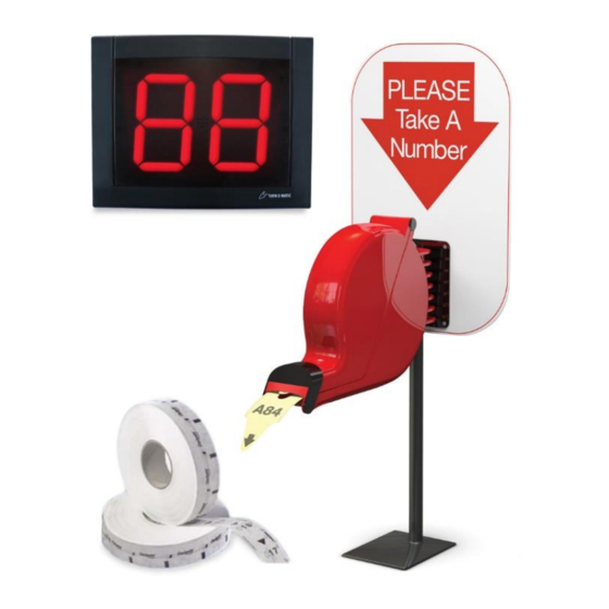
- Page 2 SYSTEM PARTS LIST WIRED SYSTEM PARTS LIST (2) Data Cable Connector (3) Large Slotted (1) Flat Display (1) Dispenser (1) Dispenser (1) Power (100’) Screw Wall Mount Mounting Connector Electrical Wire (2) Large Slotted Bracket Bracket Bolt (2) Nut (3) Push Button (1) 2 Digit Indicator (2) Large (2) Wall...
-
Page 3: Operation
OPERATION & INSTALLATION DISPENSER PARTS LIST STAND MOUNTING OPERATION 1. Position the mounting stand in the desired 1. The customer takes a number from the dispenser; location on a countertop this number will indicate the customer’s spot in the 2. Align the holes in the sign and the mounting queue bracket with the holes in the post. - Page 4 OPERATION & INSTALLATION DISPLAY PARTS LIST ELECTRONIC DISPLAY WALL MOUNTING Figure 9 Figure 8 1. Identify a suitable position for the indicator assuring the display is easily seen by the customers 2. Measure and mark the mounting holes on the wall WIRING PUSH using the display wall mount bracket as a template (Figure 6)
- Page 5 OPERATION & INSTALLATION DISPLAY CONT. PLUGGING DATA WIRING AC POWER CONNECTORS INTO SUPPLY TO POWER DISPLAY CONT. CONNECTOR 1. The power connector has two parts. Loosen both small screws using the mini flathead screwdriver 2. Insert one wire end into each port. Tighten screws to secure wires (Figure 14) Figure 11 Figure 14...
-
Page 6: Display Start-Up
OPERATION & INSTALLATION DISPLAY CONT. OPTIONAL DISPLAY START-UP DISPLAY SET-UP CONT. Once powered on, the display will show a number of messages upon start-up (Figure13) SET DISPLAY SLEEP TIME: DISPLAY SHOWS • Display shows “SL” followed by the current Program Version: “P-”, then number delay time in minutes.
Need help?
Do you have a question about the TURN-O-MATIC and is the answer not in the manual?
Questions and answers