NuTone ILF120 Installation Instructions Manual
In-line fans
Hide thumbs
Also See for ILF120:
- Installation instructions (5 pages) ,
- Architectural & engineering specifications (2 pages) ,
- Selection manual (36 pages)
Advertisement
Quick Links
In-Line Fans
MODELS: ILF120, ILF130, ILF250
IMPORTANT SAFETY INSTRUCTIONS
WARNING: TO REDUCE THE RISK OF FIRE. ELECTRIC
SHOCK, OR INJURY TO PERSONS, OBSERVE THE
FOLLOWING:
A. Use this unit only in the manner intended by the manufacturer. If
you have questions, contact the manufacturer.
B. Before servicing or cleaning unit, switch power off at service
panel and lock service panel to prevent power from being
switched on accidentally.
When the service disconnecting means cannot be locked, securely
fasten a prominent warning device, such as a tag, to the service
panel.
• Suitable for use with solid state speed controls.
CAUTION: For general ventilating use only. Do not use to exhaust
hazardous or explosive materials and vapors.
INSTALLATION INSTRUCTIONS
WARNING: TO REDUCE THE RISK OF FIRE, ELECTRIC
SHOCK, OR INJURY TO PERSONS, OBSERVE THE
FOLLOWING:
A. Installation work and electrical wiring must be done by qualified
person(s) in accordance with all applicable codes and standards,
including fire-rated construction.
B. Sufficient air is needed for proper combustion and exhausting of
gases through the flue (chimney) of fuel burning equipment to prevent
back drafting. Follow the heating equipment manufacturer's guideline
and safety standards such as those published by the National Fire
Protection Association (NFPA), and the American Society for
Heating, Refrigeration and Air Conditioning Engineers (ASHRAE),
and the local code authorities.
C. When cutting or drilling into wall or ceiling, do not damage electrical
wiring and other hidden utilities.
D. Ducted fans must always be vented to the outdoors.
E. NEVER place a switch where it can be reached from a tub or shower.
FOR BEST RESULTS
To ensure quiet operation of ENERGY STAR qualified inline fans,
each fan shall be installed using sound attenuation techniques
appropriate for the installation. For bathroom and general ventilation
applications, at least 8 feet of insulated flexible duct shall be
installed between the exhaust or supply grille(s) and the fan.
When installing the Ventilator in a new construction site, install
fan and ducting during the rough-in construction of the building. Inlet
grille(s) should be installed after the finished ceiling is in place.
To install a ventilator in an existing building requires access to
the attic area above the space to be ventilated.
INSTALLATION IN A NEW
CONSTRUCTION SITE
MOUNTING
1. Select a mounting site; Identify a mounting location that offers
accessibility with minimal duct run. Mount ventilator as far from
the inlet grille as practical to minimize noise.
READ & SAVE THESE INSTRUCTIONS!
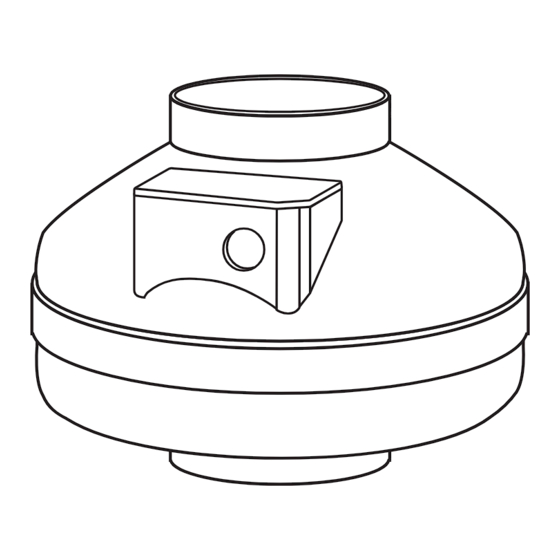
MOUNTING BRACKET
FAN MOUNTING
FIGURE 1
2. Attach fan mounting bracket to the support joist using the wood
screws provided (Refer to Figure 1). For best performance
vertical mounting is recommended, however any orientation is
acceptable.
3. Attach fan to the mounting bracket using the self threading
screws provided (Refer to Figure 1). To ease attachment
pilot holes may be used for the mounting screws.
WIRING
1. Run 120v AC house power wiring through switch box to junction
box in ventilator housing.
2. Remove ventilator junction box cover.
3. Refer to Figure 2. Connect the house power wire (black) to the
terminal marked L. Connect the house neutral wire (white) to the
terminal marked N (see wiring diagram). The fan housing is fully
insulated and therefore no grounding is required.
4. Replace outlet box cover.
5. Connect house power wire to the wall switch.
NOTE: ALL WIRING MUST COMPLY WITH LOCAL
ELECTRICAL CODES.
DUCTING INSTALLATION
1. Refer to Figure 3. Attach duct to ventilator inlet and outlet using
clamps, fasteners and/or duct tape. Observe the following
recommendations for best results;
A. Always minimize duct lengths and turns.
B. When flexible ducting is used be sure that the duct is fully
stretched and free of kinks or sharp bends.
C. Use insulated ducting when passing through unconditioned spaces.
D. When insulated ducting is used clamp or tape the inner vinyl core to
the inlet and outlet of the fan and tape the vapor barrier surrounding the
duct insulation to the fan housing.
E. Always install a damper at the inlet grilles.
1
INSTALLATION INSTRUCTIONS
JOIST OR STUD
1
⁄
˝
16
Advertisement

Related Manuals for NuTone ILF120


Summary of Contents for NuTone ILF120
-
Page 1: Important Safety Instructions
INSTALLATION INSTRUCTIONS READ & SAVE THESE INSTRUCTIONS! In-Line Fans JOIST OR STUD MODELS: ILF120, ILF130, ILF250 IMPORTANT SAFETY INSTRUCTIONS WARNING: TO REDUCE THE RISK OF FIRE. ELECTRIC SHOCK, OR INJURY TO PERSONS, OBSERVE THE FOLLOWING: A. Use this unit only in the manner intended by the manufacturer. If you have questions, contact the manufacturer. -
Page 2: Care And Maintenance
SEAL DUCT SPACES TO FAN WITH DUCT TAPE AIR FLOW DAMPERED SLEEVE CEILING JOIST SEAL GAPS INLET GRILLE AROUND SLEEVE DUCTING INSTALLATION Rev. 01/14, Part No. 100933E NuTone puts everything within reach. Check out the collection of RV hardware we offer.
Need help?
Do you have a question about the ILF120 and is the answer not in the manual?
Questions and answers
It's not obvious how the ILF120 is supposed to sit in the mounting bracket. Do the mounting screws just screw right into the plastic fan housing?