Table of Contents
Advertisement
Advertisement
Table of Contents

Related Manuals for Zeversolar Zevercom WIFI

Summary of Contents for Zeversolar Zevercom WIFI
-
Page 2: Table Of Contents
Contents Contents About this Manual .................. 3 Scope of Application ....................3 Target Reader ......................3 Abbreviations ......................3 Introduction .................... 4 Product Overview ....................4 Function and Features ..................5 Scope of Application ................... 5 Scope of Delivery ....................5 Environment ...................... - Page 3 ZeverCloud website ................51 Account Registration ..................51 Create a PV plant ....................52 Browse PV plant....................53 Add a ZeverCom/ZeverCom WiFi .............. 54 PV plant Sharing ....................54 Configuration Report ..................55 Trouble Shooting .................. 57 LED Indication ....................... 57 LED Indication of Network Interface............
-
Page 4: About This Manual
We reserve the right to make changes or to update our product to introduce new functions and overall improvements. This specification is subject to change without prior notice. Please contact Zeversolar to confirm the latest revision. 1.1 Scope of Application This manual applies to the ZeverCom/ZeverCom WiFi firmware version 16B21- 663R+16B21-658R and later versions. -
Page 5: Introduction
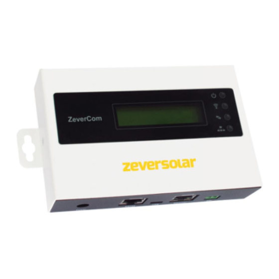
2.1 Product Overview The ZeverCom/ZeverCom WiFi collects the inverter’s data and events in the PV plant. When an Internet connection is present, the ZeverCom/ZeverCom WiFi will upload the collected data to the ZeverCloud to facilitate on-line web monitoring and data analysis. -
Page 6: Function And Features
Zverlution Pro 30K/33K The sections marked with an * apply to the ZeverCom WiFi. 2.4 Scope of Delivery Upon opening the packing box of the ZeverCom/ZeverCom WiFi you will see the following components, as shown in Table 2-1. ~ 5 ~... -
Page 7: Environment
2.5 Environment The ZeverCom/ZeverCom WiFi operational ambient temperature is -10 ° C to 60 ° C Do not allow the ZeverCom/ZeverCom WiFi to become damp or wet during use Sudden disconnection of power to the ZeverCom/ZeverCom WiFi or... -
Page 8: Indication
Indication 3. Indication 3.1 LED Indication The ZeverCom/ZeverCom WiFi displays the operating status to the user via LEDs. The LED indicator panel is showed in Fig.3-1. 192.168.6.100 ZeverCom WiFi 11:20 04/11/2014 zeversolar Fig. 3-1: LED indicator panel The meanings of the LEDs are shown in the following Table 3-1. -
Page 9: Lcd Indication
Each information screen is displayed for 2 seconds. The various information screens are shown in Table 3-2. Table 3-2: Information Screens shown on the LCD LCD indication Description 192.168.6.100 ZeverCom/ZeverCom WiFi’s IP address, time and date 11:20 04/11/2014 Disconnected ZeverCom/ZeverCom WiFi is not connected to the ZeverCloud ZeverCloud... -
Page 10: Installation
ZeverCom/ZeverCom WiFi temperatures, immersing in water, fire and strong impacts will damage the ZeverCom/ZeverCom WiFi To take advantage of the ´ s self-powered feature the ZeverCom/ZeverCom WiFi maximum length of the RS485 cable between the ZeverCom/ZeverCom WiFi the inverter is 20m.Should a separate power supply unit be used, the maximum... - Page 11 Step5: Insert the screw anchors into the drill holes using a rubber mallet. Step6: Screw in the screws until they protrude by 5mm. Fig. 4-3: Screw in the screws Step7: Hang the ZeverCom/ZeverCom WiFi on the screws. Step8: Tighten the screws. Fig. 4-4: Tighten the screws...
-
Page 12: Connection
(RJ45 LAN connectors) and not to the RS485 port. 5.2 Connection Area The ZeverCom/ZeverCom WiFi collects inverter(s) data and events, and uploads them to the ZeverCloud via the Internet. This section shows how to connect with the inverter and ZeverCloud. -
Page 13: Connecting The Power
Fig. 5-2, with the RS485 cable. Step 2: Connect the inverter closest to the ZeverCom/ZeverCom WiFi to the RS485 port of the ZeverCom/ZeverCom WiFi (Item B in Fig. 5-1) as shown in Fig. 5-2. ~12~... - Page 14 The RS485 pin assignment of the RJ45 socket is shown in Table 5-3. Table 5-3: RJ45-RS485 pin assignment Signal description 1. The RS485 port between the ZeverCom/ZeverCom WiFi and the inverter (Item C in Fig. 5-1) uses the RJ45 socket. Please make sure to use the correct port.
-
Page 15: Connecting The Energy Meter
Connection 5.5 Connecting the energy meter ZeverCom/ZeverCom WiFi can connect to Eastron smart energy meter to limit the exported power of a PV plant. The energy meter must be connected at the grid connection point, as shown in Fig. 5-4. - Page 16 Connection Fig.5-5: Connection Energy Meter The pin order of the Meter port of the ZeverCom/ZeverCom WiFi is shown in Fig. 5-6. Fig. 5-6: Socket definition The Meter port pin assignment is shown in Table 5-4. Table 5-4: Meter port pin assignment...
-
Page 17: Connecting To The Ethernet
Inverter_2 Inverter_5 Fig. 5-7: Network connection The ZeverCom/ZeverCom WiFi is connected to the network by simply connecting the network cable from the router to the Ethernet port of ZeverCom/ZeverCom WiFi (Item E in Fig. 5-1), as shown in Fig. 5-8. - Page 18 Connection The ZeverCom/ZeverCom WiFi obtains an IP address from the router via DHCP automatically and displays it on the LCD. The time it takes to connect to the network depends on the network communication conditions. The router needs to support DHCP services therefore the DHCP services must be activated.
-
Page 19: Connecting To The Wifi
Connection 5.7 *Connecting to the WiFi If users use the ZeverCom WiFi’s WiFi to connect to the router for remote monitoring, the connection diagram is shown in Fig. 5-9. WiFi Internet Internet ZeverCom WiFi Wireless Router Zevercloud Fig. 5-9: WiFi connection In order to achieve remote monitoring reliably, the following steps must be taken. - Page 20 Step4: Enter the password of the wireless local network that you wish to connect to. Do not enter the password of the router. Step5: After approximately three minutes the WiFi of the ZeverCom WiFi will connect to the wireless local network. The status indicator on the Wireless page...
-
Page 21: Connecting To Drms
Connection Connecting to DRMs The inverter shall detect and initiate a response to all supported demand response commands according to AS/NZS 4777.2:2015. The demand response modes are described as follows: Table 5-5: DRMs requirement Mode Requirement DRM 0 Operate the disconnection device DRM 1 Do not consume power DRM 2... - Page 22 Connection Fig. 5-13: DRMs RJ45 Connection Circuit The DRMs function parameters setting, please refer to 6.4.1. ~ 21 ~...
-
Page 23: Web Server
ZeverCom/ZeverCom WiFi’s internal web page, as shown in Fig. 6-2. 6.1.2 *Connecting via WiFi If you want to connect to the ZeverCom WiFi via WiFi, please refer to section 5.8. Once connected to the ZeverCom WiFi enter“160.190.0.1” in the browser’s address bar, press the Enter key to display the ZeverCom/ZeverCom WiFi’s... -
Page 24: Home
Web Server Fig. 6-2: ZeverCom/ZeverCom WiFi Web Server 6.2 Home This page shows the information and state of the ZeverCom/ZeverCom WiFi equipment. It also shows the state of the connected inverter´ s which is shown in Fig. 6-2. If the inverter is working normally, it shows a green icon;... -
Page 25: Ethernet
6.3 Ethernet Clicking the “Ethernet” tab takes you to the Ethernet page of the ZeverCom/ZeverCom WiFi´ s internal web page. From this page set the Ethernet parameters can set by either using a static IP address or obtaining the IP address automatically. - Page 26 Web Server 1. Please make sure the inverter AC capacity is correct, otherwise the power limitation function cannot work properly. Fig. 6-5: Set Active Power Limitation Method The following ways will introduce how to configure the three kinds of power limitation.
- Page 27 Web Server The Fig. 6-6 Set parameters based on the AC capacity Table 6-1: The indicator of the Item Parameter Definition The sum of the rated power of all inverters in the PV plant (Wac) The percentage of power output limitation based on parameter b Power Limitation Based on the Energy Meter Reading ...
- Page 28 Web Server Step 2: Select “limit output power based on the energy meter reading” and set out put power<=0W Step 3: Select the correct smart meter of the PV sysem Setp 4: Click the “OK” button in bottom-right of this web page to ensure the setting parameters take effect.
- Page 29 Web Server The Fig. 6-8: Set parameters based on the energy meter reading The “output power” value is e when P >= P_meter Table 6-2: The indicator of the Item Parameter Definition The sum of the rated power of all inverters in the PV plant (Wac) It expect power reading of the energy meter The energy meter model...
- Page 30 Reactive Power Limit There are four modes of reactive power limitation which can be selected. Cos(phi) fix mode: In this mode, the ZeverCom/ZeverCom WiFi will regulate the reactive power of inverter according to the Cos(phi) value which is set by the user.
- Page 31 Lagging 0.95 Fig. 6-14: Cos(phi) variable Cure Q fix mode: In this mode, the ZeverCom/ZeverCom WiFi will regulate the reactive power of the inverter according to the Q value which is set by the user. You need to input the Q value and choose the phase as shown in Fig.
- Page 32 Web Server Q variable mode: In this mode, the ZeverCom/ZeverCom WiFi will produce a curve according to the “U/Un”, “Q value” and phase position of points 1,2,3 and 4, and will regulate the reactive power according to this curve, as shown in Fig.
- Page 33 Fig. 6-18: Safety Parameters 6.4.3 Updating Firmware The firmware of the ZeverCom/ZeverCom WiFi can also be updated. It can also update the inverter’s firmware. Enter the Advanced page and click the “choose file” in the Update Firmware section to select the new firmware and then click the “OK”...
- Page 34 Web Server Fig. 6-19: Update Firmware 6.4.4 Restart Enter the Advanced page of the ZeverCom/ZeverCom WiFi and click the “OK” button at the Restart section to restart the device. Fig. 6-20: Restart ZeverCom/ZeverCom WiFi 6.4.5 Restore to Factory Enter the Advanced page of the ZeverCom/ZeverCom WiFi and click the “OK”...
-
Page 35: Wireless
Fig. 6-21: Restore to Factory This operation will delete all user data 6.5 *Wireless This page shows the list of wireless Networks that ZeverCom/ZeverCom WiFi can connect to. If you want to change the connected WiFi network, please refer to section5.7. - Page 36 This page shows the WiFi SSID and password information, you can change the SSID and WiFi password accordingly (default password is ‘zeversolar’). To ensure highest security of your system, please change the default password ‘zeversolar‘ and keep the new password confidential. If you do not change the password, you...
-
Page 37: Zevercloud App
7. ZeverCloud APP ZeverCloud APP is a terminal application used on smartphone for users provided with a Zeversolar ZeverCom / ZeverComWiFi data loggers. These data loggers transfer the operational data to the ZeverCloud server via the internet and enable the users to monitor their PV plants and inverters remotely via a smart mobile device. - Page 38 ZeverCloud APP the ZeverCloud APP or via the ZeverCloud website. Monitoring can then be performed after the user has registered and created a PV plant. Step 1: Open ZeverCloud APP which has been downloaded and installed on your device, as shown in fig. 7-3. Fig.
- Page 39 ZeverCloud APP Step 2: Click the button marked with a ‘1’ in Fig. 7-3 to enter the login page, as shown in Fig. 7-4 Fig. 7-4: Login Step 3: Click the button marked with a ‘1’ in Fig. 7-4, click ‘Register’ to enter the registration page, input the available e-mail address and login password ~38~...
- Page 40 ZeverCloud APP (Password length must be over 6 digits and less than 32 digits, capital and small English letter A(a)-Z(z) and numbers 0-9 can be accepted). Fig. 7-5: Registration Step 4: After the registration has been completed, ZeverCloud will send an activation e-mail.
-
Page 41: Create A Pv Plant
ZeverCloud APP 7.2 Create a PV plant Step 1: Open ZeverCloud APP which has been downloaded and installed already, as shown in Fig. 7-3 Step 2: Click the button marked with a ‘1’ in Fig.7-3 to enter the login page, as shown in Fig.7-4 Step 3: Input your user name and password in the area as shown in Fig.7-4 to login to ZeverCloud APP. - Page 42 ZeverCloud APP Fig.7-6: PV plant list Step 4: Click the “Create New Plant” button in the navigation bar at the bottom of the screen as shown in Fig. 7-6 to enter the PV plant create page as shown in Fig. 7-7.
- Page 43 The serial number and registry number of the monitoring device can be entered by clicking the scan button marked with a ‘1’ as shown below to scan the QR code on the label of monitoring device (ZeverCom/ZeverCom WiFi). Fig.7-7: Create a PV plant...
-
Page 44: Connect Monitoring Management Device Through Wifi
7.3 Connect Monitoring Management Device through WiFi Keep APP logging in. Open WLAN configuration on your mobile devices, search WiFi SSID of your ZeverCom. The default WiFi SSID of ZeverCom starts with ZEVERSOLAR-XXXX, i.e.: Testing SSID: ZEVERSOLAR-8894 as shown in fig. 7-8 below: ~ 43 ~... - Page 45 ZeverCloud APP Fig.7-8: Wireless network list Click SSID of ZeverCom, type in password as shown in fig (default password: zeversolar). ~44~...
- Page 46 ZeverCloud APP Fig. 7-9: Enter the password Smartphone connected to ZeverCom successfully, as shown in fig. 7-10. ~ 45 ~...
- Page 47 ZeverCloud APP Fig.7-10: Connected to the WiFi Click the ‘Connect WIFI’ button in the navigation bar at bottom as shown in Fig. 7-7 to enter the WiFi configuration page as shown in Fig.7-11. Here you can modify the WIFI password of the monitoring devices, as well as modify the account name and password of the router.
-
Page 48: Browse Pv Plant
ZeverCloud APP Fig. 7-11: WiFi configuration Before open the page of “Connect WIFI”, make sure you have manually connected your terminal mobile device to the WiFi of the monitoring device. 7.4 Browse PV plant You can enter any PV plant by clicking the plant list as shown in Fig.7-6.This allows you to view the power generation data of the PV plant as well as inverter events. - Page 49 ZeverCloud APP Fig.7-12: Menu structure of PV plant monitoring page 7.4.1 Overview This menu provides summarized information such as current Power, Total Income, E-Today, E-Month, E-Total as well as power generation charts like, current day real-time power, current month’s daily power, current year’s monthly power, annual summarized power generation, as shown in Fig.
- Page 50 ZeverCloud APP 7.4.2 Charts This menu provides detailed curve graphs, i.e: DC input voltage Vpv, DC input current Ipv and AC output power Pac of the PV plant and every inverter, as shown in Fig.7-14: Fig.7-14: Charts ~ 49 ~...
- Page 51 ZeverCloud APP 7.4.3 Devices This menu provides the status of monitoring devices, as well as other contents such as relevant parameter error information of inverters that are connected to this monitoring device, as shown in Fig.7-15 Fig.7-15: Devices ~50~...
-
Page 52: Zevercloud Website
ZeverCloud website 8. ZeverCloud website The ZeverCloud is a cloud service platform for users provided by Zeversolar. The ZeverCom/ZeverCom WiFi transfers the operation data to the ZeverCloud server via the Internet to enable the users to monitor their PV plants and inverters remotely through a computer or a mobile device. -
Page 53: Create A Pv Plant
ZeverCloud website Step 3: After the registration has been completed, ZeverCloud will send an activation email. Activate your ZeverCloud account according to the information in the email. If there is no activation mail in your inbox, please check your spam box. -
Page 54: Browse Pv Plant
ZeverCloud website Fig. 8-3: Enter the ZeverCom/ZeverCom WiFi and PV plant information to finish the creation of PV plant During PV plant creation, it is very important to choose the correct time zone. Please select the correct time zone where the PV plant is located in Position 4 shown in Fig. -
Page 55: Add A Zevercom/Zevercom Wifi
This menu provides detailed information of each inverter’s work state. 8.4 Add a ZeverCom/ZeverCom WiFi A ZeverCom/ZeverCom WiFi can be added to a PV plant as follows: Step1: Login to ZeverCloud and enter Configuration→Device Management page. Step2: Enter the serial number and registry key of the ZeverCom/ZeverCom WiFi into the textbox shown in Fig. -
Page 56: Configuration Report
ZeverCloud website Step1: Login into ZeverCloud and enter the Configuration→Shared Configuration page. Fig. 8-6: PV plant sharing Step2: Click , an “Add a shared user window” will appear; enter the user account that needs to be shared. Step3: In the check box in Fig. 8-6, you can configure the authorities of the shared users. - Page 57 ZeverCloud website Fig. 8-7: Activate the configuration report Step3: After the above steps, click the “Save” button to save your settings, then click “Test” button to send to an email immediately. ~56~...
-
Page 58: Trouble Shooting
Ensure the connect to the Wifi has been set in accordance with router section 5.6 Green off System error Restart ZeverCom/ZeverCom WiFi Red light Inverter did not send Check that the connection between does not data inverter and ZeverCom/ZeverCom... -
Page 59: Lcd Indication
Trouble Shooting 9.3 LCD Indication The LCD information of the ZeverCom/ZeverCom WiFi can help with troubleshooting as follows: Display Solutions 169.254.1.100 The ZeverCom/ZeverCom WiFi cannot obtain IP from router, 11:20 04/11/2014 please check the Ethernet cable or the router. Total INV:05... -
Page 60: Faq
ZeverCloud. “Disconnected Zevercloud” means the ZeverCom/ZeverCom WiFi is disconnected from the ZeverCloud. Q3. Why can’t I open the web page of the ZeverCom/ZeverCom WiFi’s web server? Check whether the IP address displayed on the LCD of ZeverCom/ZeverCom WiFi and the IP address of the computer are in the same network segment. -
Page 61: Technical Parameters
Technical Parameters 10. Technical Parameters Model A10078-10 A10078-00 Electrical Data Power supply DC: 7.5V~12V, Max. 0.3A DC: 7.5V~12V, Max. 0.3A Max. power 2.5W 1.5W consumption Communication Communicate with the 4-wires RS485 4-wires RS485 inverter Communicate with 2-wires RS485 2-wires RS485 energy meter Communicate with Ethernet... -
Page 62: Disposal
Disposal 11. Disposal This symbol on the product or on its packaging indicates that this product must not be disposed of with your other household waste. Instead, it is your responsibility to dispose of your old equipment by handing it over to a designated collection point for the recycling of waste electrical and electronic equipment. -
Page 63: Contact Us
Contact Us 12. Contact Us If you have any technical problems concerning our products, please contact SMA service. SMA New Energy Technology (Jiangsu) Co., Ltd Tel.: +86 512 6937 0998 Fax: +86 512 6937 3159 E-mail: service.china@sma-solar.com Factory add.: No.588 Gangxing Road, Yangzhong Jiangsu, China Headquarters add.: Building 9 No.198 Xiangyang Road, Suzhou 215011, China ~62~...
Need help?
Do you have a question about the Zevercom WIFI and is the answer not in the manual?
Questions and answers