Table of Contents
Advertisement
Available languages
Available languages
_____________________________________________________________________________
NODE 1
NODE 1
NODE 1
NODE 1
ARTNET/DMX NODE
BEDIENUNGSANLEITUNG
BEDIENUNGSANLEITUNG
BEDIENUNGSANLEITUNG
BEDIENUNGSANLEITUNG
USER MANUAL
USER MANUAL
USER MANUAL
USER MANUAL
www.eurolite.de
www.eurolite.de
www.eurolite.de
www.eurolite.de
Advertisement
Table of Contents

Related Manuals for EuroLite ARTNET/DMX NODE 1


Summary of Contents for EuroLite ARTNET/DMX NODE 1
- Page 1 _____________________________________________________________________________ NODE 1 NODE 1 NODE 1 NODE 1 ARTNET/DMX NODE BEDIENUNGSANLEITUNG BEDIENUNGSANLEITUNG BEDIENUNGSANLEITUNG BEDIENUNGSANLEITUNG USER MANUAL USER MANUAL USER MANUAL USER MANUAL www.eurolite.de www.eurolite.de www.eurolite.de www.eurolite.de...
- Page 2 • Stand-alone operation possible with 16 built-in light programs • 2 x 8-digit LCD screen for menu settings • Terminals for connecting the LEDs • Powered via included PSU • Rugged black metal housing Art-Net™ is a trademark by and Copyright Artistic Licence Holdings Ltd www.eurolite.de...
-
Page 3: Table Of Contents
6 APPLICATIONS ................... 21 DMX .............. 21 ONTROLLING STRIPS VIA ............21 ONTROLLING STRIPS VIA ............ 22 ONTROLLING IGHT FFECTS VIA ............22 PERATION WITHOUT XTERNAL ONTROL 7 CLEANING AND MAINTENANCE .............. 23 8 TECHNICAL SPECIFICATIONS ..............23 ....................23 CCESSORY www.eurolite.de... -
Page 4: Einführung
EINFÜHRUNG Wir freuen uns, dass Sie sich für ein Produkt von EUROLITE entschieden haben. Wenn Sie nachfolgende Hinweise beachten, sind wir sicher, dass Sie lange Zeit Freude an Ihrem Kauf haben werden. ACHTUNG! Gerät vor Feuchtigkeit und Nässe schützen! Lesen Sie vor der ersten Inbetriebnahme zur eigenen >>... -
Page 5: Sicherheitshinweise
Das Gerät darf nicht in Betrieb genommen werden, nachdem es von einem kalten in einen warmen Raum gebracht wurde. Das dabei entstehende Kondenswasser kann unter Umständen Ihr Gerät zerstören. Lassen Sie das Gerät solange ausgeschaltet, bis es Zimmertemperatur erreicht hat! Kinder und Laien vom Gerät fern halten! www.eurolite.de... -
Page 6: Bestimmungsgemässe Verwendung
Sicherheitsgründen verboten sind. Wird das Gerät anders verwendet als in dieser Bedienungsanleitung beschrieben, kann dies zu Schäden am Produkt führen und der Garantieanspruch erlischt. Außerdem ist jede andere Verwendung mit Gefahren, wie z. B. Kurzschluss, Brand, elektrischem Schlag, etc. verbunden. www.eurolite.de... -
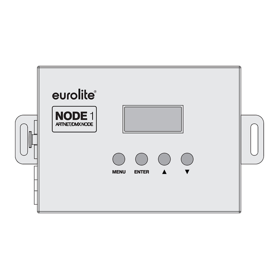
Page 7: Bedienelemente Und Anschlüsse
BEDIENELEMENTE UND ANSCHLÜSSE Klemmanschlüsse für die LEDs DMX-Ein- und Ausgang (3-polig XLR) Display Bedientasten Netzanschluss Ethernet-Schnittstellen (RJ-45) www.eurolite.de... -
Page 8: Menü
Eingabe des Subnetteils Bereich 3 0-255 Eingabe des Subnetteils Bereich 4 1-32768 Eingabe des DMX-Universums Geräteeinstellungen Option BLGT Display-Beleuchtung immer an BLGT Display-Beleuchtung nach 20 s aus BRCO 0-100 Display-Helligkeit SYSRESET Gerät zurücksetzen (zusätzlich die Tasten ▲ und ▼ kurz drücken) www.eurolite.de... -
Page 9: Inbetriebnahme
Mögliche Anzahl Pixel im DMX-Betrieb (je Konverter) LED-Streifen Verbinden Sie das beiliegende Netzteil mit der Anschlussbuchse DC IN am Gerät und stecken Sie es in eine Steckdose (100-240 V~, 50/60 Hz). Das Gerät ist damit eingeschaltet. Zum Ausschalten den Netzstecker wieder trennen. www.eurolite.de... -
Page 10: Dmx-Einstellungen
Startadressen der nachfolgenden Geräte sind abhängig von der Anzahl der DMX-Kanäle, die diese belegen. Belegt jedes Gerät bspw. 20 Kanäle, stellen Sie das erste Gerät auf Startadresse 1 ein und die nachfolgenden Geräte auf ein Vielfaches von 20 (21, 41, 61 usw.). www.eurolite.de... -
Page 11: Anwendungsmöglichkeiten
Computernetzwerk. Schalten Sie ggf. mehrere Konverter in Reihe. Schließen Sie die LED-Streifen an die Klemmen OUTPUT an. Mappen Sie die LED-Streifen in der Software (unter MADRIX mit dem Generator oder Patch). Steuern Sie die LED-Streifen mit der Software ( Dokumentation der Software). www.eurolite.de... -
Page 12: Lichteffekte Per Art-Net Steuern
Für Automatikbetrieb mit den integrierten Lichtprogrammen wählen Sie im Menü den Modus „Prog Run“ und die Nummer des gewünschten Programms. Im Untermenü „Speed“ lässt sich die Ablaufgeschwindig- keit der Programme einstellen und mit der Option „Flash“ ein Strobe- Effekt zuschalten. www.eurolite.de... -
Page 13: Reinigung Und Wartung
Klemmen Reihenschaltung: max. 50 Konverter DMX-Steuerung: max. 170 Pixel Art-Net-Steuerung: max. 170 Pixel (RGB-LEDs) max. 128 Pixel (RGBA-/RGBW-LEDs) Maße (LxBxH): 153 x 90 x 37 mm Gewicht: 350 g Zubehör 50530200 LED IP Pixel Strip 160 5m RGB 12V www.eurolite.de... -
Page 14: Introduction
INTRODUCTION Thank you for having chosen a EUROLITE product. If you follow the instructions given in this manual, we are sure that you will enjoy this device for a long period of time. Please keep this manual for further needs. -
Page 15: Safety Instructions
If the device has been exposed to drastic temperature fluctuation (e.g. after transportation), do not switch it on immediately. The arising condensation water might damage your device. Leave the device switched off until it has reached room temperature. Keep away children and amateurs! www.eurolite.de... -
Page 16: Operating Determinations
If this device will be operated in any way different to the one described in this manual, the product may suffer damages and the guarantee becomes void. Furthermore, any other operation may lead to dangers like short-circuit, burns, electric shock, crash etc. www.eurolite.de... -
Page 17: Operating Elements & Connections
OPERATING ELEMENTS & CONNECTIONS Terminals for the LEDs DMX input and output (3-pin XLR) Display Operating buttons Power input Ethernet ports (RJ-45) www.eurolite.de... -
Page 18: Menu
1-32768 Input the DMX universe number System settings Option BLGT Display backlight always on BLGT Display backlight off after 20 sec BRCO 0-100 Display brightness SYSRESET Reset unit to factory settings (press buttons ▲ and ▼ to start reset) www.eurolite.de... -
Page 19: Setting Into Operation
Connect the power supply unit provided to the power input DC IN on the device and to a mains socket (100-240 V~, 50/60 Hz). Thus the node is powered on. By disconnecting the unit from the mains it can be switched off. www.eurolite.de... -
Page 20: Dmx Settings
1. The start addresses of the following units depend on the number of DMX channels each unit occupies. For example, if each fixture occupies 20 channel, set the first unit to 1 and the following units to a multiple of 1 (21, 41, 61 etc.). www.eurolite.de... -
Page 21: Applications
Connect the LED strips to the OUTPUT terminals. Map the LED strips in your software (under MADRIX e.g. with the Generator or Patch). Control the LED strips with the software ( documentation of the software). www.eurolite.de... -
Page 22: Controlling Light Effects Via Art-Net
Adjust the desired flash frequency under “Flash“. For automic mode with a built-in light program, select the mode “Prog Run“ and the number of the desired program. In the submenus, adjust the running speed of the program and the flash frequency. www.eurolite.de... -
Page 23: Cleaning And Maintenance
50 nodes DMX control: max. 170 pixels Art-Net control: max. 170 pixels (RGB LEDs) max. 128 pixels (RGBA/RGBW LEDs) Dimensions (LxWxH): 153 x 90 x 37 mm Weight: 350 g Accessory 50530200 LED IP Pixel Strip 160 5m RGB 12V www.eurolite.de... - Page 24 © © © © EUROLITE 201 EUROLITE 2015 5 5 5 EUROLITE 201 EUROLITE 201 Technische Änderungen ohne vorherige Ankündigung und Irrtum vorbehalten. Every information is subject to change without prior notice. 00090934.DOCX Version 1.1 www.eurolite.de...
Need help?
Do you have a question about the ARTNET/DMX NODE 1 and is the answer not in the manual?
Questions and answers