Table of Contents
Advertisement
Advertisement
Table of Contents

Related Manuals for Myenergi eddi


Summary of Contents for Myenergi eddi
- Page 1 Rev 1.0 August 2017...
-
Page 3: Table Of Contents
Contents Introduction............................4 Safety....................................4 Overview..................................5 Box Contents...................................5 Operation..............................7 Controls & Indicators...............................7 Display.....................................8 Operating Modes................................10 Manual Boost................................11 Boost Timer...................................12 Menus..............................14 Main Menu..................................14 Advanced Menu................................15 Relay & Sensor Menu..............................16 Configuration............................19 Settings..................................19 Advanced Settings.................................20 Linking Devices................................21 Installation............................23 Wiring....................................24 Sensor Installation.................................26 Relay & Sensor Board..............................28 Fitting the Cover................................29 Setup.....................................30 Application Examples..........................31... -
Page 4: Introduction
Introduction Introduction Thank you for choosing eddi . Of course, we think you have made an excellent choice and are sure you will be very happy with the features, benefits and quality of this myenergi product. eddi is an automatic power controller for heaters. It 'tracks' available surplus power from a grid-tied PV or Wind turbine system and varies the power to the heater to match the surplus power, therefore ensuring all of the green energy is fully utilised. -
Page 5: Overview
Box Contents ◦ 1x eddi unit with mounting bracket attached ◦ 1x Current Transformer with 5m cable (Grid Sensor) ◦ 1x Antenna ◦ 1x Operation & Installation Manual... - Page 6 Introduction eddi operation and installation manual...
-
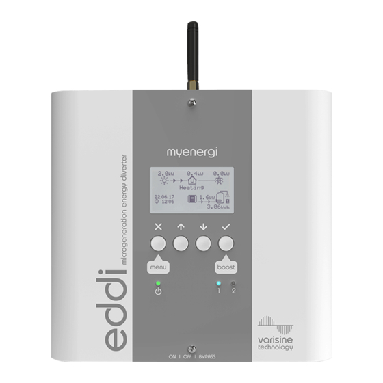
Page 7: Operation
If both 1 & 2 are lit together, the heaters are at maximum temperature ON/OFF and BYPASS switch This switch has three positions: eddi is on (this is the normal position) eddi is off (the power on indicator will be off) -
Page 8: Display
Message Icon When this icon is present there is a message from the myenergi server This only applies if you have the myenergi hub device Date & Time The current date and time Status Icons These icons indicate that the import limiting is active (house), a relay is on (R1 /... - Page 9 Power Flow Direction – Large Amount Import Power Limiting Active Waiting For Surplus Power Relay 1 or 2 – On Maximum Heater Temperature Reached Economy Tariff Electricity Available eddi Device – Normal Active Heater Number eddi Device – Too Warm (output limited) Instantaneous Power...
-
Page 10: Operating Modes
Operation Operating Modes Waiting for Surplus eddi is waiting for surplus power from the microgeneration system. The house in the centre is straight faced as grid electricity is being used by the house (0.8kW is this example). We can see that... -
Page 11: Manual Boost
Press to start boost The boost duration may be altered by pressing during the boost Cancelling Manual Boost The boost can be cancelled at by pressing twice eddi operation and installation manual... -
Page 12: Boost Timer
Operation Boost Timer eddi can be programmed to 'boost' the heating for each heater at certain times. Boost, means that the heater will be at full power regardless of the amount of available export power. This means that power may be drawn from the mains grid supply during boost times. - Page 13 (See Priority on page 19). If one or more boost times conflict for one heater, the boost will follow the latest time or longest duration. Cancelling Boost The boost can be cancelled at by pressing twice during a boost. eddi operation and installation manual...
-
Page 14: Menus
Date and time of last recorded fault code Fault Date: INFORMATION Network ID: Network information for this device when linked to other devices using RF network Device Address: (Only shows if connected to other devices) Master Address: Channel: EUI: eddi operation and installation manual... -
Page 15: Advanced Menu
Settings for some devices are made here - See Linking Devices (page 21) Pairing Mode… Puts this eddi in pairing mode so it can be linked to another device - See Linking Devices (page 21) Add a myenergi device to the 'network'. See See Add Device…... -
Page 16: Relay & Sensor Menu
Heating… Heating 1 Operates Relay 1 when Heater 1 output is live Heating 2 Operates Relay 1 when Heater 2 output is live eddi operation and installation manual... - Page 17 Destrat 1 De-stratification pump control for Heater 1; the Relay 2 operates when is trying to heat Heater 1 and eddi the heater is at maximum temperature. After Check Period the relay will deactivate Destrat 2 De-stratification pump control for Heater 2; the Relay...
- Page 18 The eSense input will act as an enable for the Boost 1&2 Timer for Heater 1 and 2. The Boost Timer has an additional parameter 'e', when this option is set See Boost Timer page 12 eddi operation and installation manual...
-
Page 19: Configuration
The date and time are used for the Boost Timer and the savings calculations and therefore should be set correctly. In the event of a power-cut, eddi will still keep track of the time and date for a few days, so when power is restored the clock will not need to be reset. -
Page 20: Advanced Settings
Supply Grid - Phase The Phase setting is only used on 3-phase systems. It should be set to match the phase number that the eddi is wired to so that the power measurements are correct and that eddi responds to the correct phase when using the harvi wireless sensor. -
Page 21: Linking Devices
– An self-powered wireless sensor that can be used along with myenergi load controlling devices such as eddi zappi and is able to report the grid or generation power information to the other devices wirelessly, this can greatly simplify installation. - Page 22 Device Priorities The priority of each, load controlling linked device, can be set from any device with a display. This enables control of how the surplus energy is shared between them. The example below shows one eddi device, two zappi...
-
Page 23: Installation
Installation Installation Mounting eddi is NOT suitable for installation outdoors. • Ensure the device always has adequate ventilation; do not block the vents or obstruct the airflow at the back of • the unit. must be fixed to a vertical surface eddi •... -
Page 24: Wiring
Supply The eddi device should be connected to a single-phase 230V or 240V nominal AC supply. The supply should be from a dedicated 16A circuit breaker, or it can be from a hard-wired 13A fused spur outlet if the heater load is less than 3kW. - Page 25 Installation eddi operation and installation manual...
-
Page 26: Sensor Installation
Grid Sensor must be on the same phase. If the generation is also three-phase and it is desired to consume surplus power on each phase, 3 eddi units can be installed provided there are suitable loads. Note: it is usually possible to split a 3-phase heating element into 3 individual elements by removing the links. - Page 27 In some cases it can be difficult or impractical to install a wired sensor. For example it may be the case that the eddi unit needs to be connected to a sub-board, rather than main consumer unit and two consumer units are in different buildings.
-
Page 28: Relay & Sensor Board
Installation Relay & Sensor Board eddi has the option to install a Relay & Sensor Board (available separately), this allows for many different wiring configurations and includes the following features: Two independent multifunction relays (16 Amp) • eSense input (isolated 230V detection for low tariff etc.) •... -
Page 29: Fitting The Cover
Installation Fitting the Cover Refit the cover and secure with the two M3x12 screws (2). Ensure the locating tabs (1) are correctly positioned inside the slots on the chassis before the cover is screwed on. eddi operation and installation manual... -
Page 30: Setup
0.0kW). Note; however, if the surplus power exceeds the rating of the heater then this cannot be achieved and some export power will be observed If power is being imported from the grid when the eddi is in Heating mode, it is likely that the Grid Sensor is improperly installed - see Grid Sensor Installation on page 26 If a Generation Sensor has been installed, the generated power will show at the top left of the main screen If the generation reading is missing, the most likely cause is the CT2 input is not enabled –... -
Page 31: Application Examples
Please refer to the Safety section (page 4) and be sure to read all of the installation sections before attempting to install the eddi A good level of electrical competence and a reasonable understanding of domestic plumbing systems is assumed for studying these application examples. -
Page 32: 1: Single Element Water Heater
Application Examples 1: Single Element Water Heater eddi operation and installation manual... - Page 33 Heating the water during times of generation (e.g. daylight hours) is best avoided to allow maximum capacity for the surplus energy. This is the default configuration for eddi; the settings do not need to be altered for this application. Settings Required...
-
Page 34: 2: Dual Element Water Heater
Application Examples 2: Dual Element Water Heater eddi operation and installation manual... - Page 35 Application Examples Key for Wiring Diagram 2 eddi device Heating element 1 (max. 3.7kW) Mains supply (230V AC from B16 circuit breaker or Isolator (20A double pole) 13A fused spur) Heating element 2 (max. 3.7kW) Hot water cylinder Functional Description...
-
Page 36: 3: Economy Tariff With Dual Rate Meter
Application Examples 3: Economy Tariff with Dual Rate Meter RLY2 RLY1 PT1 PT2 24hr eddi operation and installation manual... - Page 37 Application Examples Key for Wiring Diagram 3 eddi device Isolator (20A double pole) Mains supply (230V AC from B16 circuit breaker or Relay & Sensor Board (optional add-on for eddi 13A fused spur) Temperature probe (type PT1000) (optional) Hot water cylinder Economy rate electric sense wiring (live only when Heating element (max.
-
Page 38: 4: Economy Tariff With Separate Meters (Heater 1)
Application Examples 4: Economy Tariff with Separate Meters (Heater 1) RLY2 RLY1 PT1 PT2 24hr eddi operation and installation manual... - Page 39 Application Examples Key for Wiring Diagram 4 eddi device Isolator (20A double pole) Mains supply (24hr) (230V AC from B16 circuit breaker Relay & Sensor Board (optional add-on for eddi or 13A fused spur) Temperature probe (type PT1000) (optional) Hot water cylinder Mains supply (off-peak timed) (230V AC from B16 Heating element (max.
-
Page 40: 5: Economy Tariff With Separate Meters (Heater 2)
Application Examples 5: Economy Tariff with Separate Meters (Heater 2) RLY2 RLY1 PT1 PT2 24hr eddi operation and installation manual... - Page 41 Application Examples Key for Wiring Diagram 5 eddi device Isolator (20A double pole) Mains supply (230V AC from B16 circuit breaker or Relay & Sensor Board (optional add-on for eddi 13A fused spur) Temperature probe (type PT1000) (optional) Hot water cylinder Mains supply (off-peak timed) (230V AC from B16 Heating element (max.
-
Page 42: 6: Radiator And Water Heating
Application Examples 6: Radiator and Water Heating eddi operation and installation manual... - Page 43 Application Examples Key for Wiring Diagram 6 eddi device Heating element (max. 3.7kW) Mains supply (230V AC from B16 circuit breaker or Isolator (20A double pole) 13A fused spur) Electric radiator (150W min. 3.7kW max.) Hot water cylinder Functional Description...
-
Page 44: 7: Underfloor Heating Mat And Water Heating
Application Examples 7: Underfloor Heating Mat and Water Heating RLY2 RLY1 PT1 PT2 °C eddi operation and installation manual... - Page 45 Input setting is set to Heater Enable 2 so only when the thermostat is calling for heat will eddi apply power to the mat. When the underfloor heating thermostat is open eddi will display Max Temp Reached. Installation of the temperature probe (7) is optional; the immersion heaters' mechanical thermostat is used by eddi if water temperature reading is not required.
-
Page 46: 8: Water Heater With De-Stratification Pump
Application Examples 8: Water Heater with De-stratification Pump RLY2 RLY1 PT1 PT2 eddi operation and installation manual... - Page 47 Application Examples Key for Wiring Diagram 8 eddi device Isolator (20A double pole) Mains supply (230V AC from B16 circuit breaker or Relay & Sensor Board (optional add-on for eddi 13A fused spur) Temperature probe (type PT1000) (optional) Hot water cylinder De-stratification pump Water heating element (max.
-
Page 48: 9: Water Heater With Auxiliary Boiler Control - Y Plan
Application Examples 9: Water Heater with Auxiliary Boiler Control – Y Plan RLY2 RLY1 PT1 PT2 1 2 3 4 5 6 7 8 9 10 Y-PLAN eddi operation and installation manual... - Page 49 Application Examples Key for Wiring Diagram 9 eddi device Isolator (20A double pole) Mains supply (230V AC from B16 circuit breaker or Relay & Sensor Board (optional add-on for eddi 13A fused spur) Temperature probe (type PT1000) (optional) Hot water cylinder Y-Plan control water and heating junction box Water heating element (max.
-
Page 50: 10: Water Heater With Auxiliary Boiler Control - S Plan
Application Examples 10: Water Heater with Auxiliary Boiler Control – S Plan RLY2 RLY1 PT1 PT2 1 2 3 4 5 6 7 8 9 10 S-PLAN eddi operation and installation manual... - Page 51 Application Examples Key for Wiring Diagram 10 eddi device Isolator (20A double pole) Mains supply (230V AC from B16 circuit breaker or Relay & Sensor Board (optional add-on for eddi 13A fused spur) Temperature probe (type PT1000) (optional) Hot water cylinder Heat Pump (with immersion heater output) Heating element (max.
-
Page 52: 11: Heat Pump With Water Heating
Application Examples 11: Heat Pump with Water Heating RLY2 RLY1 PT1 PT2 eddi operation and installation manual... - Page 53 Application Examples Key for Wiring Diagram 11 eddi device Isolator (20A double pole) Mains supply (230V AC from B16 circuit breaker or Relay & Sensor Board (optional add-on for eddi 13A fused spur) Temperature probe (type PT1000) (optional) Hot water cylinder Heat Pump (with immersion heater output) Heating element (max.
-
Page 54: 12: Heat Pump With Water Heating And Buffer Tank
Application Examples 12: Heat Pump with Water Heating and Buffer Tank RLY2 RLY1 PT1 PT2 eddi operation and installation manual... - Page 55 Application Examples Key for Wiring Diagram 12 eddi device Relay & Sensor Board (optional add-on for eddi Mains supply (230V AC from B16 circuit breaker or Temperature probe (type PT1000) (optional) 13A fused spur) Heat Pump (with immersion heater output)
-
Page 56: 13: Heat Pump With Water Heating And Priority Control
Application Examples 13: Heat Pump with Water Heating and Priority Control RLY2 RLY1 PT1 PT2 eddi operation and installation manual... - Page 57 (9) needs to be connected to the eSense input of the Relay & Sensor Board (6) instead of the immersion heater element (4). In this application, the eddi is configured to respond to the eSense signal by fully switching on Heater 1 output regardless of available surplus.
-
Page 58: 14: Pool And Water Heating
Application Examples 14: Pool and Water Heating RLY2 RLY1 PT1 PT2 °C eddi operation and installation manual... - Page 59 Application Examples Key for Wiring Diagram 14 eddi device Temperature probe (type PT1000) (optional) Mains supply (230V AC from B16 circuit breaker or Swimming pool 13A fused spur) In-line electric pool heater (max. 3.7kW) Hot water cylinder Pool heater thermostat (16A rated) Water heating element (max.
-
Page 60: Troubleshooting
‐ Ensure the heater neutral conductor is are out of balance connected to “N” terminal of the “Heaters” screw terminal block in the eddi; do not use any other neutral MCB tripped or supply fuse blown ‐ Possible faulty unit ‐... -
Page 61: Fault Codes
Note: harvi will stop working if there is no power in the cable being monitored, however eddi will show this message only if there is no signal from harvi for more than 24hrs Grid Sensor Error! -
Page 62: Warranty
Subject to the provisions described below, this product is protected for three (3) years from the date of purchase against defects in material and workmanship. Prior to returning any defective product to myenergi, the end customer must report the faulty product to myenergi... -
Page 63: Technical Specifications
Painted Zintec steel Operating Temperature -20°C to +40°C Mounting Method Wall mounting bracket Designed to permit installations compliant with IET Wiring Regulations BS7671:2008+A3 2015 and the Electricity Safety, Quality, and Continuity Regulations 2002 and BS 8300:2009+A1:2010. eddi operation and installation manual... - Page 64 Designed and manufactured in the UK by MyEnergi Ltd, Church View Business Park, Binbrook, Market Rasen, LN8 6BY +44 (0)1472 398182...
Need help?
Do you have a question about the eddi and is the answer not in the manual?
Questions and answers
My emersion tank is boiling