
Subscribe to Our Youtube Channel
Related Manuals for SDMO Nexys 2

Summary of Contents for SDMO Nexys 2
- Page 1 Instructions for use SDMO Nexys 2 Réf. constructeur : V 20/09/2004 Réf. GPAO : 33502017201_1_1 1 / 22...
-
Page 2: Table Of Contents
1. Introduction to MICS Nexys .................................3 2. Description ....................................3 2.1. Standard configuration..............................3 2.1.1 Presentation of the front panel............................4 2.1.2 Introduction to pictograms...............................5 2.1.3 Introduction to the rear panel............................6 2.2. Safeguards..................................6 3. Use ........................................7 3.1. Manual mode ...................................8 3.1.1 Starting the generating set ...............................8 3.1.2 Stopping the generating set..............................9 3.2. -
Page 3: Introduction To Mics Nexys
1. Introduction to MICS Nexys MICS Nexys is a command / control module designed to control the generating set. This module, with a 12V direct current supply, is incorporated into the following control consoles: N 2500 N 3500 N 4500 Circuit breaker rating ≤... -
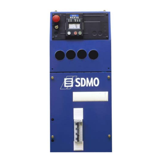
Page 4: Presentation Of The Front Panel
2.1.1 Presentation of the front panel Fig. 2.1 – View of the front side Emergency stop button for switching off the generating set in the event of a fault which could endanger personnel or damage equipment Key switch for starting up/shutting down the module and RESET function Electronic card protection fuse Screen-scroll button, press successively to access the various screens which are available STOP button, press to switch off the generating set... -
Page 5: Introduction To Pictograms
Fig. 2.2 – Description of the LEDs A lit LED indicates: Module being supplied (green, lights up and remains lit) Emergency stop activated (control panel or external emergency stop) (red, lights up and remains lit) Visualisation of starting phase and speed/voltage stabilisation (flashing) and generating set operating OK or set ready to generate (green, lights up and remains lit) General alarm (orange, flashing) General fault (red, flashing). -
Page 6: Introduction To The Rear Panel
2.1.3 Introduction to the rear panel Fig. 2.4 – View of the front side "Base" electronic card "Measurements" electronic card (optional if the power rating of the generating set is less than 30 kVA) Slot for options. 2.2. Safeguards The following options may be added to the standard configuration: Measurements card (if the power rating of the generating set is less than 30 kVA) Connected directly to the base card, used for measuring and displaying: Electrical quantities (phase-to-neutral voltages "V"... -
Page 7: Use
Horn Connected to the "horn" output (2 fast-on connectors located on the electronic card), can be used to sound an audible warning in the event of a fault of any type. A "horn off" button may be pressed to inhibit operation of the horn (only the horn). -
Page 8: Manual Mode
3.1. Manual mode 3.1.1 Starting the generating set Check that the generating set circuit breaker has triggered. Danger connect the generating set battery. turn the key switch to the ON position (without forcing it) All of the LEDs light up for 2 seconds, to confirm that they are operating correctly. If the LEDs do not light up, check the protection fuse and replace it if necessary. -
Page 9: Stopping The Generating Set
Note: the LED flashes as soon as the START button is pressed and continues to flash until the frequency stabilises if a "measurements" card has not been inserted and until the frequency and voltage stabilise if a "measurements" card has been inserted. Following stabilisation, the LED light comes on continuously. -
Page 10: Stopping The Generating Set
3.2.2 Stopping the generating set When the power is restored (controlled by the SDMO switch), there is a time delay. After this (120 seconds), the external command disappears, the "emergency" switch is triggered and the "normal" switch is deactivated. -
Page 11: Special Features Of Automatic Mode
3.3. Special features of automatic mode Pressing the "STOP" button when the external command is active ("AUT" pictogram flashing) will stop the generating set immediately in general fault mode, the general fault LED will light up flashing and the following message will appear: means S.O.S. -
Page 12: Alarms And Faults
4. Alarms and faults 4.1. Display Faults and alarms are displayed as follows: Faults LED (general fault) will flash whenever a fault occurs. In conjunction with this LED: The red LED lights up and remains lit (only for the emergency stop fault). If a pictogram appears on the LCD screen this represents the fault along with the SOS message. -
Page 13: List Of Faults Which Will Cause The Generating Set To Stop And Generate A Pictogram
4.3. List of faults which will cause the generating set to stop and generate a pictogram Associated pictogram Oil pressure fault: Indicates that the oil pressure is incorrect Associated pictogram Engine temperature fault: Indicates that the engine temperature is too high. Associated pictogram Non-starting fault: Indicates that there have been three consecutive unsuccessful starting attempts. -
Page 14: List Of Faults Which Will Cause The Generating Set To Stop And Generate A Fault Code
4.4. List of faults which will cause the generating set to stop and generate a fault code Associated message Low coolant level fault: indicates that the level of coolant is low in the radiator (linked to a two second time delay). Additional fault linked to message opposite: is displayed in the following three cases: Associated message... -
Page 15: List Of Alarms Associated With A Pictogram
4.5. List of alarms associated with a pictogram Associated pictogram Low fuel level alarm: Indicates the need to fill up with fuel. Associated pictogram "Alternator charging fault" alarm indicates a problem affecting the alternator charging rate. 5. Special notes Emergency stop If the shunt on terminal block B11 is removed (control console interior), the generating set stops immediately due to an emergency stop fault. - Page 16 Low fuel level The low fuel level pictogram flashes if the low fuel level has been configured as an alarm. The low fuel level pictogram lights up and remains lit if the low fuel level has been configured as a fault. In this case, the general fault LED flashes red.
-
Page 17: Fault Finding
6. Fault finding Probable causes Remedial action Fuel level too low Fill up with fuel Faulty module supply fuse Check and replace the fuse ON/OFF switch in "OFF" position Turn the switch to "ON" Release the emergency stop button and reset Emergency stop button pressed the fault, moving the switch to "OFF". -
Page 18: Programming Visualisation
8. Programming visualisation The MICS Nexys is factory-set for your application. The user can display this programming as follows: As soon as the Nexys module is switched on (key switch to "ON"), press until the LED test is complete (until the LEDs go out). The programming will now appear on the screen. -
Page 19: Viewing The Different Screens
Parameter label Possible parameter value(s) No display if Motor oil pressure Display if 9. Viewing the different screens When the generating set is running, various screens can be accessed. The number of screens which can be accessed depends on whether or not the "measurements" card has been inserted. Screen 1 When it is switched on, the following screen is displayed... - Page 20 • 1st press Screen 2 o The first line displays the number of operating hours. o The second line displays the number of operating minutes. • 2nd press Screen 3 o the first line displays the frequency of the AC current supplied by the generating set (Hz).
- Page 21 The following screens display the electrical quantities based on the type of application of the generating set: three-phase + N (3Ph + N) three-phase (3Ph) two-phase + N (2Ph + N) single-phase (1Ph + N) • The following screens appear the 5th time the button is pressed: o screen A: three-phase applications + N and three-phase o screen E : two-phase applications + N o screen D: two-phase applications + neutral...
- Page 22 Screen C o The first line displays the current circulating in phase 1 (A). o The second line displays the current circulating in phase 2 (A). o The third line displays the current circulating in phase 3 (A). Screen F o The first line displays the current circulating in phase 1 (A).
Need help?
Do you have a question about the Nexys 2 and is the answer not in the manual?
Questions and answers