
Subscribe to Our Youtube Channel
Related Manuals for Raise3D N2

Summary of Contents for Raise3D N2
- Page 1 Filament Run-out Sensor Installation Guide Filament Run-Out Sensor Installation Guide - N2/N2 Plus WWW.RAISE3D.COM AMERICA · ASIA · EUROPE...
- Page 2 Turn power switch to the “0” or “Off” state. Once the printer has fully shut down, unplug the power cable. STEP 2: Remove Acrylic Back Panel with Side Door Remove the back panel of the printer with a phillips head screwdriver. The attached side door will also be removed with this panel. WWW.RAISE3D.COM AMERICA · ASIA · EUROPE...
- Page 3 Filament Run-out Sensor Installation Guide Set the panel and screws aside. N2: 10 screws N2 Plus: 11 screws STEP 3: Replace the Bowden Tube 1) If the original Bowden Tubes on your printer are with 4mm-OD: Remove the original Bowden tubes completely and replace them with the included Bowden tubes from the Run-Out Kit (D).
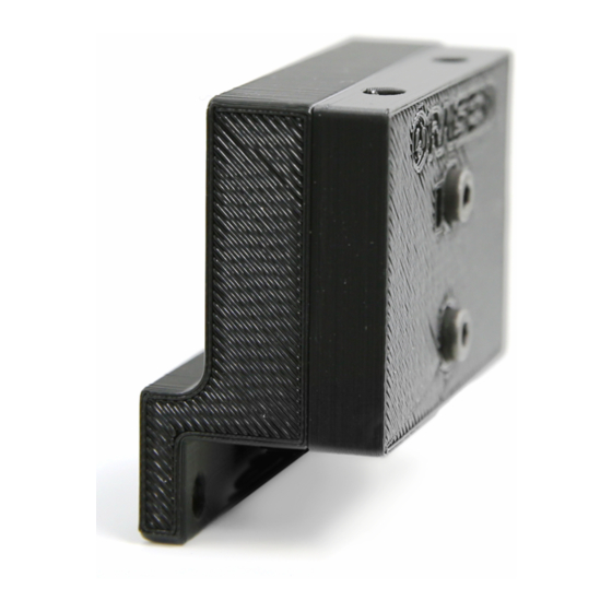
- Page 4 Adjust the height of the sensor until the top screw is hidden by the body of the printer, and the top of the bottom screw lies flush along the panel. WWW.RAISE3D.COM AMERICA · ASIA · EUROPE...
- Page 5 If there is no removable cover on the wiring guide tube of your printer, please inset the end of the cable into the gap between guide tube and bottom cover. Then drag it into the electronic box. (See Right) WWW.RAISE3D.COM AMERICA · ASIA · EUROPE...
- Page 6 Feed the end of this cable down under the printer and loop the cable back up into the electrical compartment. Use the included adapter (C) to connect the Filament Run-Out Sensor to the motion controller board with the 4-pin end. WWW.RAISE3D.COM AMERICA · ASIA · EUROPE...
- Page 7 Attach the other three ends of the adapter onto the Motion Controller Board as shown in the following pictures: Red-black cable to EXP3 (slot on terminal face to right), White Cable to Z+, Green Cable to Y+. Wiring complete: EXP3 WWW.RAISE3D.COM AMERICA · ASIA · EUROPE...
- Page 8 Back Panel and door (Step 2) STEP 11: Attach All Removed Parts Please download Motion Board Firmware with FRS version and Version 0.9.7 Touchscreen Firmware from https://www.raise3d.com/pages/download. Continue to the “Motion Controller Firmware Update” for instructions on how to update to the latest firmware.
Need help?
Do you have a question about the N2 and is the answer not in the manual?
Questions and answers