
Related Manuals for Systems & Technology careu u1 plus

Summary of Contents for Systems & Technology careu u1 plus
-
Page 1: User Guide
CAREU U1 PLUS User Gu CAREU U1 PLUS User Guide Version: 0.1 Reference No.: AVL Date: 2014/12/26 SYSTEMS & TECHNOLOGY COR... - Page 2 General Information If any breakdown occurs due to the operation of the described product or users’ improper handling in accordance with the instructions of the document, S&T shall be liable for the General Conditions based on the delivery of the described product and the content of the document. This product is not designed for the use of life support appliances, devices or systems and thence a malfunction of the product might reasonably be expected to make personal injury.
-
Page 3: Table Of Contents
1.3 Overview ..................... 1 1.4 Hardware Architecture ................3 1.5 Related Document ..................3 Chapter 2 Taking a Tour of CAREU U1 PLUS ........... 4 2.1 Dimensions ....................4 2.2 PIN Assignment .................... 4 Chapter 3 Getting Started with CAREU U1 PLUS ..........6 3.1 Device Configuration.................. -
Page 4: Chapter 1 Introduction
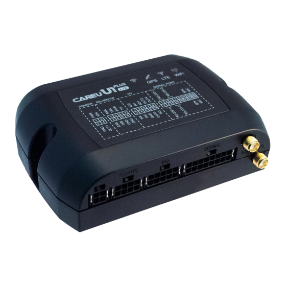
Peripheral data indicates the status of various peripherals connected to and/or controlled by the device. Among the best features of the CAREU U1 PLUS Vehicle Tracker, in particular, they transmit data in ASCII mode (Intellitrac X Series compatible mode) or binary mode. - Page 5 GPS LED GSM LED Power Connector RS-485/CAN Connector I/O Connector Serial Connector GSM Antenna Connector GPS Antenna Connector Reset Switch 10. RJ45 Connector 11. Remote Receiver Connector...
-
Page 6: Hardware Architecture
1.4 Hardware Architecture As hardware is concerned, the CAREU U1 PLUS is comprised of a micro-controller, regulator, GPS receiver, 2G/3G modem, G-Force sensor, flash memory data storage. ● Users can connect PC's Hyper Terminal to the diagnostic setting port for the configuration. -
Page 7: Chapter 2 Taking A Tour Of Careu U1 Plus
Chapter 2 Taking a Tour of CAREU U1 PLUS 2.1 Dimensions Dimensions (L x W x H): 72mm x 108mm x 31mm 2.2 PIN Assignment POWER RS-485 / CAN SERIAL PORT PWR Connector Pin# Signal Name Description Electrical Characteristic DC IN... - Page 8 SERIAL Connector Pin# Signal Name Description Electrical Characteristic Supply voltage Vout1 Vo = 5V ( Vout 1~2 Total Imax = 500mA ) output Signal ground RS232 Data output RS232 Data input Supply voltage Vout2 Vo = 5.0V, (Vout1~2 Total Imax = 500mA) output Signal ground RS232 Data output...
-
Page 9: Chapter 3 Getting Started With Careu U1 Plus
Chapter 3 Getting Started with CAREU U1 PLUS To install the the CAREU U1 PLUS device, follow the instructions below for basic operations 3.1 Device Configuration 1. Connected the serial port 1 to PC COM port 2. In Windows desktop, click Start | All Programs | Accessories | Communications | HyperTerminal. - Page 10 Stop Bits --> 1 Flow Control --> None 7. In the connection that you have just set up, click File | Properties. Select the [Connect To] tab. From the [Connect using] drop down list, select the correct com port. 8. In the File menu, click Properties. Click the [Settings] tab. Press the ASCII Setup button.
- Page 11 9. In the [ASCII Sending] group box. Select both Send line ends with line feeds and Echo typed characters locally. Press the OK button. 10.Connect your the CAREU U1 PLUS device and power on,The device startup message will be displayed.
-
Page 12: Communication Settings
3.2 Communication Settings The CAREU U1 PLUS Vehicle Tracker communicates with your control center by either SMS or 2G/3G (TCP/UDP). Before the device is installed into a vehicle, communication parameters should be set. -
Page 13: Gps Tracking Configurations
AT$IPTYPE=1 (Using TCP/IP mode) OK AT$GPRSEN=1 (GPRS enable) OK AT$HB=60,1 (Heartbeat setting) OK Please refer to the CAREU U1 PLUS Protocol Document for more command details. 3.3 GPS Tracking Configurations After the device communication settings are done, the remote GPS tracking is ready to function. - Page 14 For simple testing GPRS, run the TCP Server U-Series software which is provided by S&T. It is simple server software that can wait for device connection and data. For advanced testing, you need the software Intelli TracerPlus. Please request this software through your sales contact.
-
Page 15: Firmware Upgrade
3.4 Firmware Upgrade The firmware of the CAREU U1 PLUS can only be updated through USB interface. With the firmware loader tool provided by S&T, firmware update can be done for the device. Such firmware loader runs on Windows-based systems. To upgrade the firmware, follow the procedure below 1. -
Page 16: Chapter 4 Technical Specification
Press browse the button to browse to the firmware provided by S&T. Press the Start button to run the firmware program. After the writing progresses to 100%, it takes about 20 seconds for the update to completes. Firmware update completes. Chapter 4 Technical Specification Hardware Description... - Page 17 Digital Input x 5: 1 High Active( ACC) 2 Negative Trigger 2 Positive /Negative Digital Output x 4 Sink Current=300mA Maximum Communication RS-232 X 2 (Standard) RS485 X 1 (Full Duplex/ *Half Duplex setting by BOM) Interface CAN X 1 Net Working 10/100 Ethernet MAC with dedicated DMA: supports IEEE 1588v2 hardware, RMII...
- Page 18 Systems & Technology Corp. (S&T), founded in 1987, is a market leader in Automatic Vehicle Locating (AVL) solutions, Geographical Information Systems (GIS) and navigation. It has formed a professional development team to innovate the most advanced and comprehensive GPS tracking products for the customers and has built a global service network to provide non-stop services and support.
-
Page 19: Chapter 5 Regulation
Chapter 5 Regulation Federal Communication Commission Interference Statement This device complies with Part 15 of the FCC Rules. Operation is subject to the following two conditions: (1) This device may not cause harmful interference, and (2) this device must accept any interference received, including interference that may cause undesired operation. -
Page 20: Chapter 6 Safety Information
Radiation Exposure Statement: This equipment complies with FCC radiation exposure limits set forth for an uncontrolled environment. This equipment should be installed and operated with minimum distance 20cm between the radiator & your body. Chapter 6 Safety Information...
Need help?
Do you have a question about the careu u1 plus and is the answer not in the manual?
Questions and answers