Table of Contents
Advertisement
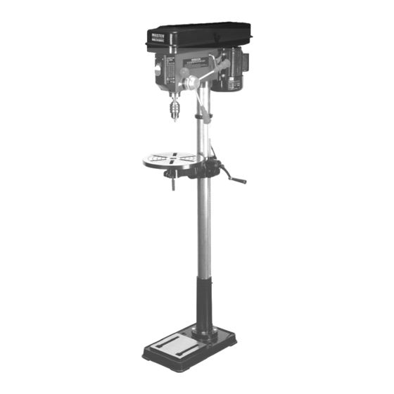
PRODUCT SPECIFICATIONS
Rating:
No-load speed:
Maximum drilling depth:
Spindle speed:
Chuck:
Table diameter
Table tilting:
Base size
Column diameter:
Distance spindle/column:
Distance spindle/table
Distance spindle/base
Need Assistance?
Call us on our toll free customer support line:
1-866-349-8665 Monday – Friday from 9am to 5pm
Eastern Standard Time
•
Technical questions
•
Replacement parts
•
Parts missing from package
Manufactured For and Distributed By
®
True Value
Company
Chicago, IL 60631-3505
©2014 True Value Company
Made in China
120 V, 60 Hz, 6.6A
1750/min
80mm (3-1/8")
16 speed ˜210-3840/min ¯
16 mm (5/8")
290mm (11-3/8")
0° to 45°
70mm (2-3/4")
170mm (6-5/8")
780mm (30-5/8")
1210mm (47-5/8")
13" DRILL PRESS
Owner's Manual
183619
Advertisement
Table of Contents

Related Manuals for master mechanic 183619


Summary of Contents for master mechanic 183619
- Page 1 13” DRILL PRESS 183619 Owner’s Manual PRODUCT SPECIFICATIONS Rating: 120 V, 60 Hz, 6.6A No-load speed: 1750/min Maximum drilling depth: 80mm (3-1/8”) Spindle speed: 16 speed ˜210-3840/min ¯ Chuck: 16 mm (5/8”) Table diameter 290mm (11-3/8”) Table tilting: 0° to 45°...
-
Page 2: Safety Instructions
SAFETY INSTRUCTIONS NOTE: Before using the tool, read the Owner’s Manual carefully. WARNING! To prevent personal injury, do not connect the machine to the power source until the machine is completely assembled and you have read and understood the entire instruction manual. Always disconnect the plug from the power source before assembling parts, making adjustments or changing drill bits. -
Page 3: General Safety Rules
GENERAL SAFETY RULES WARNING: READ ALL INSTRUCTONS. Failure to footwear and hair nets for long hair are follow the SAFETY RULES listed BELOW and other recommended. basic safety precautions may result in serious 11. ALWAYS USE SAFETY GLASSES and a face or personal injury. -
Page 4: Electrical Requirements
WARNING: when plugging or unplugging the power General Electrical Connections cord, hold the plug by its body keeping the fingers Use only grounded 3-prong sockets. See Fig.A away from the terminals. 183619 Head Assembly Column Bracket assembly Base Column support flange... -
Page 5: Assembly Instructions
ASSEMBLY INSTRUCTIONS WARNING: For your own safety, do not plug the power cord to the power source until all assembly steps have been completed. ASSEMBLY OF BASE/COLUMN • Locate base (#4), column support flange (#5) and Slide the bracket assembly into the rack and column (#2). -
Page 6: Installing The Table
INSTALLING THE FEED HANDLES Locate three feed handles (#8). Screw the feed handles tightly into the threaded holes in the hub. (Fig 12) INSTALLING THE TABLE Locate table (#11) and remove the protective paper. Place the table on the arm of bracket assembly INSTALLING THE CHUCK (Fig. -
Page 7: Depth Adjustment
ADJUSTMENTS TABLE ADJUSTMENT Mounting The Drill Press Your drill press must be securely fastened through the two holes in the base (1) to a level Push the chuck up on the arbor nose as far as it floor using heavy-duty fasteners. This will prevent will go (Fig 17). -
Page 8: Belt Tension Adjustment
OPERATION AND TROUBLE SHOOTING INSTALLATION OF BITS Fixed Depth Loosen scale set knob. Turn feed shaft to lowest Insert bit shank into chuck jaws about 1” (25mm). point then rotate spindle depth to desired depth When using a small bit do not insert it so far that the and retighten the scale set knob. -
Page 9: Tool Maintenance
With the wrench in the notch, loosen the large nut until the notch disengages from boss. Do not remove this nut (Fig. 28) Carefully turn wrench clockwise to increase tension, counterclockwise to decrease tension and engage next notch in the boss. Tighten large nut with a wrench only enough to engage boss. - Page 10 Exploded View...
-
Page 11: Parts List
PARTS LIST Item# Description Item# Description Q’ty Base Spindle pulley Column support V-belt O-685 Flat washer 10 Thin nut M24x1.5 Spring washer 10 Tapping screw T3.5x10 Bolt M10x30 Switch Socket head cap screw M10x10 Flat washer 5 Column Junction box Rack Screw M4x8 Handle knob... - Page 12 Support arm Cross-shaped screw M6x10 Table locking handle Pulley adjusting Handle cover Idler pulley Socket head cap screw M6x10 V-belt O-625 Flat washer 16 Ball bearing 6202 Bolt M16x25 Retainer ring 35 Drill chuck Pulley cover knob Arbor Pulley cover Spindle Cross-shaped screw M5x12 Ball bearing 6005...
Need help?
Do you have a question about the 183619 and is the answer not in the manual?
Questions and answers