Advertisement
Quick Links
Autopilot – User's manual
Electrical connection
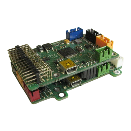
Autopilot works exclusively in combination with the OSD. All electrical
connections between the OSD and autopilot PCBs are made through a
dedicated connector on both PCBs. When purchasing a set, the two units
are electrically and mechanically connected to each other.
Autopilot can be connected to a remote control in two ways, depending
on the characteristics of the receiver and the autopilot settings.
Parallel connection of the receiver
Remote control receivers with autonomous outputs of all signals
(parallel) are connected with the autopilot in such a way that the outputs
of appropriate channels of the receiver are connected with the
corresponding input channels of the Autopilot.
NOTE: The remote control kits from different manufacturers may have
different signal sequence-for specific control elements (ailerons, gas,
direction, altitude), so connecting further signals to the autopilot, you
© Pit Lab 2017
https://www.pitlab.com/fpv-system/autopilot.html
should pay attention to the meaning of the output from the receiver and
inputs of the autopilot.
The receiver should be connected to all the control signals, and at least
one ground and power supply wire (it is not necessary to connect all pins
of the ground and the power supply). The autopilot should also be
connected to the RSSI signal if the receiver is equipped with such output.
Page 1 of 21
Advertisement

Summary of Contents for PitLab Autopilot
- Page 1 Parallel connection of the receiver Remote control receivers with autonomous outputs of all signals (parallel) are connected with the autopilot in such a way that the outputs of appropriate channels of the receiver are connected with the corresponding input channels of the Autopilot.
- Page 2 (camera control) If you use a receiver equipped with serial PPM output (CPPM) or S-Bus, connection of all channels to the autopilot can be made by a single signal RC signal diversity cable. In this case, we connect to the receiver a ground pin, power, CPPM To avoid problem with RC link on long distances the both serial inputs or S-Bus and RSSI signal if the receiver is equipped with such output.
-
Page 3: Gps Connection
Autopilot – User's manual GPS Connection Using the OSD -Autopilot set it is advisable to switch the GPS connector from the OSD board into connector on autopilot PCB. In such case the GPS system is supplied by a pulse-UBEC (like servos), relieving the linear regulator circuit on OSD (less heat is generated on the OSD board), and reducing the power consumption of the video set. - Page 4 Autopilot board does not have to be fixed exactly in the model’s center of gravity, we can choose other convenient place in the hull of the model. Figure 1 Correct locations of the autopilot inside the model ©...
- Page 5 NOTE: The greater the mass of an isolated element, the vibrations are The first step is to select the type of model tail in OSD menu autopilot -> more effectively limited, so it is best to mount flexibly the whole Mixer "sandwich"...
- Page 6 Therefore, after any change to reverse of the rudder the autopilot for about 1 second swings the rudder like to turn to the right. If after the change of the reverse you see the rudder turn left, it means that the reverse is not valid.
-
Page 7: Autopilot Modes
The center-channel (pulse duration 1.3 ms to 1.7 ms): STAB - stabilization mode If the autopilot is connected to only one aileron signal (input # 1 "aileron 1"), the autopilot transmits the same signal on both ailerons outputs - ... - Page 8 Autopilot in stabilization mode does not hold directly the setpoint direction of flight, but by keeping the level of the model largely eliminates the unplanned deviations from the current model course. Figure 7 Illustration of operation of inclination stabilization algorithm The correct setting of the stabilization of the model is necessary to work in autonomous mode of the autopilot.
- Page 9 Limit corkscrew, etc.). In autonomous mode, the autopilot is flying to the point specified by the position of the throttle (gas channel modulation). Also the distance and the course displayed on the OSD are always relative to the currently selected destination (base, waypoint or point of circulation).
- Page 10 (or waypoint) the autopilot makes a is high, and with getting closer to the expected course the speed of turn turning maneuver performed in order to return to the right course.
- Page 11 Autopilot – User's manual The slowdown in turn can be set in the OSD Autopilot-> turn slow-down. The slowdown in turn NOTE: When using the magnetic heading it is not necessary to slow Since small values of the maximum model banking can cause problems in...
- Page 12 In certain situations, such as descent from a very high altitude and the gas rod can cause incorrect handling of gas by the autopilot (e.g., forced flight with much gas, autopilot also uses the elevator to lower the exceeding the set limit of gas). Writing a non-zero position of the gas is altitude.
-
Page 13: Gas Mode
Minimum altitude: If at the AUTO mode activation the current altitude of customize the behavior to specific model and the modeler’s expectations. the model is less than the specified value, the autopilot will rise model to On-off mode is designed to glider models. In this mode the motor is the preset minimum altitude and will continue to fly at that altitude. - Page 14 , the course indicated by the speed) the autopilot can also use the value of the gas set above the limit GPS becomes the opposite to the direction the model is heading. The of gas.
- Page 15 GPS determines the course on the basis of the position of the model as in AUTO mode the autopilot takes over the role of RC transmitter and calculated in the consecutive points in time. So it is always the actual...
- Page 16 Autopilot – User's manual Choosing GPS or barometric altimeter Autopilot allows you to select the type of altimeter, which is used to time in the direction of the base flies in an arc and at the end of the flight maintain altitude in AUTO mode and indicates the altitude of on-screen is always hitting the base against the wind.
- Page 17 Autonomous flight along the points along the route is activated by a used for a flight on a particular route, both in controlled flight and change in autopilot mode to AUTO and lifting the gas rod to the middle autonomous flight.
- Page 18 Microsoft and installed on your system: http://www.microsoft.com/downloads/pl-pl/details.aspx? Once the FPV manager application is started, go to the Autopilot tab. If FamilyID=333325fd-ae52-4e35-b531-508d977d32a6 the device is connected to your computer, it be the automatically...
- Page 19 Because gyroscope measures rotation speed during calibration autopilot function, and additional PPM Aux2 to AUX5 outputs. process the autopilot (or whole plane with it) has to be very stable, not exposed to any movement nor vibration. Position of autopilot Calibrations during calibration is not important.
- Page 20 Calibrating magnetometer Principle of magnetometer calibration is to find minimal and maximal magnetic field value for all axis. To do it, the autopilot board (or whole plane with it) should be oriented to the magnetic north direction in 3 different position to calibrate all 3 axis.
- Page 21 To calibrate Z axis first enter 0 into “Zero Z” field and press “Manual Z” button. Next rotate the autopilot by 90° to be laying on side (plane should have one wing down, another up (not important which one) so the Z axis should indicate no gravity.
Need help?
Do you have a question about the Autopilot and is the answer not in the manual?
Questions and answers