Table of Contents
Advertisement
INSTALLATION AND OPERATION MANUAL
ADJUSTABLE SPEED DRIVES
for use with 1/4 - 3 HP 3-Phase Induction Motors
115, 208/230 or 380 - 460 Volts, 50/60 Hz, 1 & 3 Phase AC Line Input
Panel Mount IP-20: KBE2-1125-P, 1150-P, 1101-P, 2125-P, 2150-P
NEMA-4 / IP-65: KBE2-1125-4, 1150-4, 1101-4, 2101-4
The information contained in this manual is intended to be accurate. However, the
manufacturer retains the right to make changes in design which may not be included herein.
KBE2 DIGITAL AC
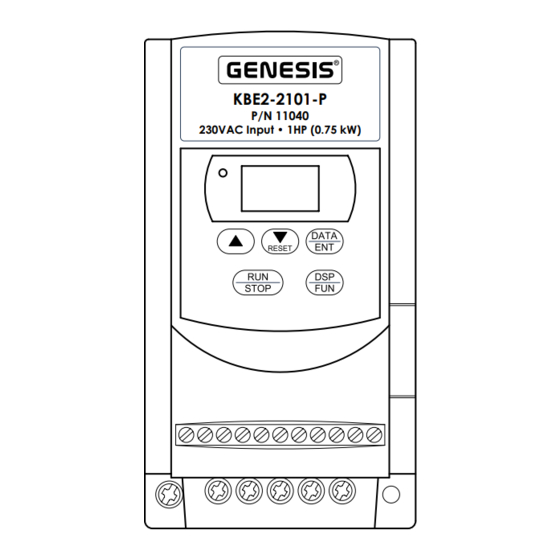
KBE2-2101-P
P/N 11040
230VAC Input • 1HP (0.75 kW)
This Manual Covers
2101-P, 2202-P, 2203-P, 4301-P, 4302-P, 4303-P
2202-4, 2203-4, 4301-4, 4302-4, 4303-4
!
See Safety Warning on page 6
Automation and Control
LISTED
16KJ.
POWER CONV.EQ
E177007
ISO
9002
Note: This drive has
been programmed
to operate 60 Hz
motors. For 50 Hz
motor operation,
see Section VIII-C
and Table 11 on
page 30.
© 2003 KB Electronics, Inc.
(See back cover)
Advertisement
Table of Contents

Subscribe to Our Youtube Channel
Related Manuals for Genesis KBE2


Summary of Contents for Genesis KBE2
- Page 1 Section VIII-C and Table 11 on page 30. This Manual Covers Panel Mount IP-20: KBE2-1125-P, 1150-P, 1101-P, 2125-P, 2150-P 2101-P, 2202-P, 2203-P, 4301-P, 4302-P, 4303-P NEMA-4 / IP-65: KBE2-1125-4, 1150-4, 1101-4, 2101-4 2202-4, 2203-4, 4301-4, 4302-4, 4303-4 See Safety Warning on page 6 The information contained in this manual is intended to be accurate.
-
Page 2: Table Of Contents
TABLE OF CONTENTS Section Page Simplified Instructions ..........5 Safety Warning . - Page 3 KBE2-2202-P, 2203-P, 4301-P, 4302-P, 4303-P (Pkg. B) ....13 1C. Mechanical Specifications for Models KBE2-1125-4, 1150-4, 1101-4, 2101-4 (Pkg. C) ..... . 14 1D. Mechanical Specifications for Models KBE2-2202-4, 2203-4, 4301-4, 4302-4, 4303-4 (Pkg.
- Page 4 TABLE OF CONTENTS (Continued) Figures Page 5B. External Start/Stop-Forward/Reverse Open Collector Connections ..20 6A. SW1 Set for Remote Speed Potentiometer or Voltage Following Signal Input . 21 6B. SW1 Set for Current Following Signal Input ......21 Remote Speed Potentiometer Connection .
-
Page 5: Simplified Instructions
SIMPLIFIED INSTRUCTIONS WARNING! These instructions are to be used as a guide only after reading the complete instructions contained herein. Important Application Information: It is recommended that this drive be used with Inverter Duty or TENV motors which provide full rated torque over an extended speed range without overheating. -
Page 6: Safety Warning
The KBE2 is available in IP-20 Panel Mount and NEMA-4 / IP-65 (indoor) enclosures. They operate 3-phase AC induction motors thru 3 HP. Several models are available with 115, 208/230, and 380/460 Volts AC - 50/60 Hz AC line input. - Page 7 Other functions include (3) pre- set speeds, analog output signal (0 - 10 Volts DC), and a programmable output relay. The KBE2 also contains the following protection features: undervoltage, overvoltage, overtemperature, ground fault, short circuit, and I t motor overload protection.
- Page 8 Note: All models are available with a built-in Class A Industrial Standard RFI Filter. Contact Sales Department. • Brake Resistor Kit – Provides rapid stopping of the drive. Available for Models KBE2-2202, 2203, 4301, 4302, 4303. • DIN Rail Mounting Kit • DownLoad Module™ (DLM) – Uploads and downloads drive programs.
-
Page 9: Electrical Ratings
Sec. I – Introduction (Cont.) - Page 10 Sec. I – Introduction (Cont.)
-
Page 11: General Performance Specifications
Class A Industrial — Notes: 1. Models KBE2-1125-P, 1150-P, 2150-P, 2101-P do not contain a braking transistor. 2. Models KBE2- 2202, 2203, 4301, 4302, and 4303 require optional brake resistor to achieve maximum braking. Maximum brak- ing torque varies with model. 3. Proportional to the Output Frequency Upper Limit set with F06. -
Page 12: Model Number Identification
4: 460V 3: 3φ 03: 3 HP Indoor *Available for NEMA-4 / IP-65 Models Only. FIGURE 1A – MECHANICAL SPECIFICATIONS (Inches/mm) for Models KBE2-1125-P, 1150-P, 1101-P, 2125-P, 2150-P, 2101-P (Pkg. A) DATA 4.56 RESET STOP 5.20 Drive Depth is 4.65 0.18... -
Page 13: Mounting Instructions
FIGURE 1B – MECHANICAL SPECIFICATIONS (Inches/mm) for Models KBE2-2202-P, 2203-P, 4301-P, 4302-P, 4303-P (Pkg. B) 5.04 DATA RESET STOP 5.63 4.25 0.18 3 x ∅ 4.65 6.77 Drive Depth is MOUNTING INSTRUCTIONS It is recommended that the drive be mounted vertically on a flat surface with ade- quate ventilation. -
Page 14: Kbe2-1125-4, 1150-4, 1101-4, 2101-4 (Pkg. C)
Sec. II – Mounting Inst. (Cont.) FIGURE 1C – MECHANICAL SPECIFICATIONS (Inches/mm) for Models KBE2-1125-4, 1150-4, 1101-4, 2101-4 (Pkg. C) 7.83 DATA RESET STOP 8.50 4.84 0.17 4 x ∅ 5.55 6.69 Drive Depth is... -
Page 15: Kbe2-2202-4, 2203-4, 4301-4, 4302-4, 4303-4 (Pkg. C1)
Sec. II – Mounting Inst. (Cont.) FIGURE 1D – MECHANICAL SPECIFICATIONS (Inches/mm) for Models KBE2-2202-4, 2203-4, 4301-4, 4302-4, 4303-4 (Pkg. C1) DATA RESET STOP 10.85 11.65 8.25 9.15 Drive Is Shown with Optional Power On/Off Switch, Forward-Stop-Reverse Switch, and Main Speed Potentiometer. -
Page 16: Iii. Reconditioning The Bus Capacitors
III. RECONDITIONING THE BUS CAPACITORS It is recommended that the bus capacitors be reconditioned if this product has been in storage for over one year. To recondition the capacitors, apply the AC line, with the drive in the Stop Mode, for a minimum of one hour. IV. -
Page 17: Terminal Blocks Tm1 And Tm3 Wiring Information
Sec. IV – Term. Blocks TM1 and TM3 Wiring Inst. (Cont.) tial. Do not fuse neutral or grounded conductors. A separate AC line switch or contactor must be wired as a disconnect so that each ungrounded conductor is opened. See Section VI, on page 24. TABLE 4 –... -
Page 18: With 1Φ Ac Line Input
Sec. IV – Term. Blocks TM1 and TM3 Wiring Inst. (Cont.) FIGURE 3A – POWER CONNECTIONS for PKG. A and PKG. C MODELS with 1φ AC LINE INPUT Ground 3φ AC 1φ AC (Earth) Induction Motor Line Input FIGURE 3B – POWER CONNECTIONS for PKG. B MODELS with 1φ... -
Page 19: Terminal Block Tm2 Wiring Instructions (Signal Connections)
Terminals “P” and “R”, as shown in Figure 3B, on page 18. This optional brake resistor can provide maximum braking torque of up to 130% (model dependent). This option is only available for Models KBE2- 2202, 2203, 4301, 4302, and 4303. See Section X-D, on page 52. -
Page 20: External Start/Stop-Forward/Reverse Connection
Sec. V – Term. Block TM2 Wiring Inst. (Cont.) FIGURE 5A – EXTERNAL FIGURE 5B – EXTERNAL A. External START/STOP-FORWARD/ START/STOP-FORWARD/ Start/Stop- REVERSE CONNECTIONS REVERSE OPEN COLLECTOR Forward/Reverse CONNECTIONS Connection – FWD REV +12 External control of FWD REV +12 Start/Stop and Forward/Reverse is achieved by... -
Page 21: Signal Input, F11, And Sw1 Setting
Sec. V – Term. Block TM2 Wiring Inst. (Cont.) TABLE 7 – SIGNAL INPUT, F11, and SW1 SETTING Frequency Control Method F11 Code Setting SW1 Position Keypad (Factory Setting) 000 (Factory Setting) 5 kΩ Potentiometer* (Factory Setting) 0 - 10 Volts DC 0 - 20 mA DC 4 - 20 mA DC * 10 kΩ... -
Page 22: Programmable Functions For F19 And F20
Sec. V – Term. Block TM2 Wiring Inst. (Cont.) to Terminal 9, and the low side to Terminal 10, as shown in Figure 7, on page 21. Set F11 [Frequency Control Method] to “001” [Potentiometer] and be sure SW1 is set to the “V” position (factory setting). See Section IX, on page 42. 3. -
Page 23: Selecting Preset Output Frequency With Multifunction Input Terminals 6 And 7
MULTIFUNCTION INPUT Operation: Many INPUT TERMINAL TERMINAL OPEN COL- applications require CONNECTIONS LECTOR CONNECTIONS preset speed opera- tion. The KBE2 is +12 SP1 RESET +12 SP1 RESET capable of providing 3 preset fixed speeds using Terminals “6” and PRESET PRESET... -
Page 24: Multifunction Output Relay Connection
Do not install a fuse or circuit breaker in series with motor leads. TABLE 10 – RECOMMENDED FUSE OR CIRCUIT BREAKER RATING Model Rating (Amps AC) Model Rating (Amps AC) KBE2-1125 KBE2-2202 20, 15* KBE2-1150 KBE2-2203 30, 15* KBE2-1101... -
Page 25: Hi-Pot Setup
FIGURE 12 – HI-POT SETUP... -
Page 26: Recommended High Voltage Dielectric Withstand Testing (Hi-Pot)
VII. RECOMMENDED HIGH VOLTAGE DIELECTRIC WITHSTAND TESTING (Hi-Pot) Testing agencies such as UL, CSA, etc., usually require that the equipment under- go a hi-pot test. In order to prevent catastrophic damage to the drive, which has been installed in the equipment, it is recommended that the following procedure be followed. -
Page 27: Digital Keypad Layout
Sec. VIII – Drive Operation (Cont.) 3. DSP/FUN Key – The DSP/FUN key is used to change the display between Display Mode and Function Mode. a. If DSP/FUN is pressed while frequency is displayed, the display will indi- cate a function number. b. -
Page 28: Digital Keypad Operation
Sec. VIII – Drive Operation (Cont.) b. If the drive is in Stop Mode, press the L key to increase the set frequency. c. If a function number is displayed, press the L key to increase the func- tion number to the next higher number. d. -
Page 29: Flow Chart To Change Set Frequency (Drive In Stop Mode)
Sec. VIII – Drive Operation (Cont.) 2. Press the RUN/STOP key to run the drive at the new Set Frequency. Note: Figure 14 FIGURE 14 – FLOW CHART TO CHANGE SET FREQUENCY (DRIVE IN STOP MODE) is a flow chart which illustrates the sequence to change and... -
Page 30: Programming
C. Programming – All drive functions have been factory programmed, as shown in Table 15, on pages 37 and 38. Application Notes: 1. The KBE2 drive has been factory programmed for 60 Hz motors for use in constant torque applications. F05 is factory set to “004” [60 Hz Constant Torque]. - Page 31 Maintaining pressure on the L or M/RESET key will cause the display to change rapidly. The programmable range for F18 is 0.1 - 200%. Example: If a 3.3 Amp motor is used with Model KBE2-2101 (rated 4.2 Amps), F18 should be set according to the following formula.
-
Page 32: Function F23, F24, F28 Code Settings
Sec. VIII – Drive Operation (Cont.) f. Press DSP/FUN key to return to the frequency display or press the L or M/RESET key to change to another function number. Notes: 1. Programming F05 is related to the motor characteristics not the AC line input frequency (50/60 Hz). -
Page 33: All Faults Except Ac Power Loss
Sec. VIII – Drive Operation (Cont.) To change the setting of F23 from “000” to “001”: 1. The drive must be in Stop Mode (press the RUN/STOP key). The set frequency will flash on the display. 2. Press the DSP/FUN key to display function number. 3. -
Page 34: All Faults Including Ac Power Loss
Sec. VIII – Drive Operation (Cont.) c. Automatic Restart for All Faults Including AC Power Loss* – If the application requires that the drive automatically restart after a fault has cleared, including an AC power loss, Function F28 must be set as fol- lows. - Page 35 Sec. VIII – Drive Operation (Cont.) b. Press the DSP/FUN key to display function number. c. Press the L or M/RESET key until “F11” is displayed. d. Press the DATA/ENT key. The function code will be displayed (factory setting is “000” (Keypad]). e.
-
Page 36: Programmable Functions (Summary List)
Sec. VIII – Drive Operation (Cont.) WARNING! The Stop contact is never to be used as a Safety Disconnect since it is not fail-safe. Use only the AC line for this purpose. To change the setting of F03 to Run/Stop-Forward/Reverse: a. - Page 37 Sec. VIII – Drive Operation (Cont.)
- Page 38 Sec. VIII – Drive Operation (Cont.)
-
Page 39: Programmable Functions (Detailed)
IX. PROGRAMMABLE FUNCTIONS (Detailed) The KBE2 Series drive contains programmable functions which are described below. See Section VIII-A, on page 26, for keypad instructions. See Table 15, on pages 37 and 38. F01 – Acceleration Time Factory Setting: “5.00” (5.0 Seconds) – F01 is used to set the acceleration time. - Page 40 Sec. IX – Programmable Functions (Detailed) (Cont.) F04 – Motor Direction Factory Setting: “000” [Forward Direction] – F04 is used to set either forward or reverse motor direction using the keypad. F04 is factory set to “000” for forward operation of the motor. F04 = 000: Forward Direction 001: Reverse Direction Note: In order for the Reverse Function to operate, F22 must be set to “000”...
-
Page 41: Volts/Hz Pattern
Sec. IX – Programmable Functions (Detailed) (Cont.) FIGURE 16 – VOLTS/Hz PATTERN Constant Torque Application High Starting Torque Application Variable Torque (HVAC) Application Output Frequency Upper Limit (F06) Motor Frequency (%) F08 – (Preset Speed #1) Factory Setting: “10.0” (10.0 Hz) – F08 is used to set the frequency of Preset Speed #1 and is factory set to “10.0”, which will run the motor at 10.0 Hz if Terminal “6”... - Page 42 Sec. IX – Programmable Functions (Detailed) (Cont.) F10 – Start/Stop Control Factory Setting: “000” [Keypad Operation] – F10 is used to set either keypad operation or external start/stop control. F10 is factory set to “000”, which pro- vides start/stop control with the keypad. (Also see F03). F10 = 000: Keypad Operation 001: External Run/Stop Contacts Note: If F10 is set to “001”...
-
Page 43: Volts/Hz Curve Modification (Torque Boost)
Sec. IX – Programmable Functions (Detailed) (Cont.) F13 – Volts/Hz Curve Modification (Torque Boost) Factory Setting: “00.0” (0.0 %) – F13 is used to increase the percent of torque boost that will be applied to the motor by modifying the Volts/Hz patterns set by F05, as shown in Figure 17. -
Page 44: Controlled Deceleration-To-Stop With Dc Injection Braking
1.5 Hz, injection braking takes effect. For high inertial loads, the optional Brake Resistor may be required (available for Models KBE2-2202, 2203, 4301, 4302, 4303 only). See Section X-D, on page 52. If F14 is set to “000”... - Page 45 Terminal 7 of Terminal Block TM2. Programmable Range: 1 - 200% Example: If a 3.3 Amp motor is used with Model KBE2-2101 (rated 4.2 Amps), F18 should be set according to the following formula.
- Page 46 Sec. IX – Programmable Functions (Detailed) (Cont.) F19 = 004: Coast-to-Stop. The drive will coast-to-stop when a momentary “Stop” command is given. “b.b.” will flash on the display. To restart the drive, press the RUN/STOP key (if F10 is set to “000” [Keypad Operation]) or open and close the direction contact (if F10 is set to “001” [External Run/Stop Contacts]).
-
Page 47: Multifunction Output Relay Operating Modes
Sec. IX – Programmable Functions (Detailed) (Cont.) TABLE 16 – MULTIFUNCTION OUTPUT RELAY OPERATING MODES Output Relay Contacts F21 Setting Power Drive In Drive In Frequency Fault Stop Mode Run Mode Reached 001 [Run] Open Open Closed — — 002 [Frequency Reached] Open Open —... - Page 48 Sec. IX – Programmable Functions (Detailed) (Cont.) F25 – Reset Drive to Factory Settings Factory Setting: “020” [60 Hz Operation] – F25 is used to reset the drive to fac- tory settings for both 50 Hz and 60 Hz motors. F25 = 010: Reset Drive for 50 Hz Constant Torque Motor Operation 020: Reset Drive for 60 Hz Constant Torque Motor Operation Note: Setting F25 to “010”...
- Page 49 Sec. IX – Programmable Functions (Detailed) (Cont.)
- Page 50 Sec. IX – Programmable Functions (Detailed) (Cont.)
-
Page 51: Optional Accessories
Table 17, on pages 49 and 50. X. OPTIONAL ACCESSORIES A. DIN Rail Mounting Kit (Part No. 14000) – Available for all models except KBE2-1125-4, 1150-4, 1101-4, 2101-4, 2202-4, 2203-4, 4301-4, 4302-4, 4303-4. B. Class B Residential Standard RFI (EMI) Filters – Provides RFI noise suppres- sion and complies with CE Directive 89/336/EEC relating to the EMC Class B Residential Standard. -
Page 52: Recommended Rfi Filter Connection
- 5 Watt wire wound potentiometer, mounting hardware, and panel insulator. D. Brake Resistor – Provides rapid stopping with high inertial loads. See Table 20. This option is only available for Models KBE2-2202, 2203, 4301, 4302, and 4303. TABLE 20 – BRAKE RESISTOR SELECTION CHART... -
Page 53: Dlm Connections
F. Drive-Link™ Software (Part No. 14165) – Provides PC communications to facilitate programming. Uses Windows® 95/98/2000/ME/XP/NT. Requires DownLoad Module™ (DLM) (Part No. 14145) and KBE2 to DLM Serial Communication Cable (Part No. 14147). See Figure 20. For Drive-Link™ Software with USB cable, order Part No. 14166. -
Page 54: Ac Load Reactor Selection Chart
AC Line Reactors can be purchased from ACME, MTE, and TCI. TABLE 21 – RECOMMENDED AC LINE REACTOR SELECTIOIN CHART AC Line Reactor Rating AC Line Drive Model Input Phase(s) Volts AC Amps AC KBE2-2125 KBE2-2150 KBE2-2101 KBE2-2202 0.71 KBE2-2203 0.71 KBE2-4301... - Page 55 – NOTES –...
-
Page 56: Xi. Limited Warranty
KB Electronics, Inc. (8/22/02) “KB” and “GENESIS” are registered trademarks of KB Electronics, Inc. KB Electronics, Inc. 12095 NW 39th Street, Coral Springs, FL 33065-2516 • (954) 346-4900 • Fax (954) 346-3377 Outside Florida Call TOLL FREE (800) 221-6570 •...
Need help?
Do you have a question about the KBE2 and is the answer not in the manual?
Questions and answers
Can i run a1.5kw motor with a 2.2kw vfd
Yes, a 2.2kW GENESIS KBE2 Series VFD can be used to run a 1.5kW motor, provided that the motor's rated voltage matches the control output voltage (208/230V or 380/460V AC). Additionally, appropriate programming and motor protection settings, such as Motor Overload Protection (F18), should be adjusted to match the motor's specifications.
This answer is automatically generated
Will the 2.2kw VFD drive a 1.5kw electric motor
Yes, a Genesis KBE2 2.2 kW (3 HP) VFD can drive a 1.5 kW (2 HP) electric motor, as the drive supports motors up to its rated capacity.
This answer is automatically generated