Sign In
Upload
Download
Table of Contents
Contents
Add to my manuals
Delete from my manuals
Share
URL of this page:
HTML Link:
Bookmark this page
Add
Manual will be automatically added to "My Manuals"
Print this page
×
Bookmark added
×
Added to my manuals
Manuals
Brands
Comark Manuals
Gateway
RF500A
System manual
Comark RF500A System Manual
Hide thumbs
1
Table Of Contents
2
3
4
5
6
7
8
9
10
11
12
13
14
15
16
17
18
19
20
21
22
23
24
25
26
27
28
29
30
31
32
33
34
35
36
37
38
39
40
41
42
43
44
45
46
47
48
49
50
51
52
53
54
55
56
57
58
59
60
61
62
63
64
65
66
page
of
66
Go
/
66
Contents
Table of Contents
Bookmarks
Table of Contents
Table of Contents
Check Packed Items
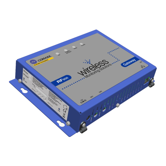
RF500A Gateway
RF500 Transmitters
RF500 Product Range
RF500 Gateway
RF500 Transmitters Are Available as Follows
RF512 Temperature Transmitter
RF512M Temperature Transmitter Backbone Option
RF513 Temperature and Humidity Transmitter
RF513M Temperature and Humidity Transmitter Backbone Option
RF515 Analog Input Transmitter and RF515A Connection Box
RF516 Precision Temperature Transmitter
RF542 Temperature Transmitter
Optional Accessories
Safety Information
Warning
Weee
Powering on and off
Switch on
Gateway Switch off
Gateway Reset
Transmitter Activation
RF500A-CONFIG - RF500A Configuration Utility
Requirements for RF500A-CONFIG
Installation of USB Drivers
Obtain Comark USB Drivers
USB Driver Installation Instructions
Installation of RF500A-CONFIG
Obtain RF500A-CONFIG Utility
RF500A-CONFIG Installation Instructions
Running RF500A-CONFIG for the First Time
Gateway Commissioning
Requirements for Commissioning
Setting of Gateway IP Address Using RF500A-CONFIG
Viewing the Gateway Login Page
Setup of First Administrator
Gateway Language
Gateway Name
Gateway Clock Setup
Network Setup
Network Details
Gateway Programming and Use
RF500 System Components
Know Your Gateway
RF500A Front Panel Indicators
Bottom Connections
Alarm Outputs
Side Switches and Indicators
Know Your Transmitter
Transmitter Display
RF542 Network Transmitter - Detailed Operation
Connections to Network
RF542 Setup Procedure
Equipment Installation
Gateway Fixing
Transmitter Fixing
Mains Wiring
Ventilation
RF500 Wireless Monitoring System Overview
Gateway - Introduction
Overview of RF500 Mesh Networking
Meshing Transmitters and Backbone Transmitters
Automatic Data Retrieval (ADR)
Gateway Specification - RF500A
Transmitters Specification
RF542 Network Specification
Changing Lithium Battery on RF500 Series Transmitters
Battery Reordering
Battery Change Procedure
Check for Transmitter Errors
Gateway Indication of Low Battery
Pinout and Wiring
Door Connector
Power Connector
Lumberg Connector
Gateway Relay Outputs
FCC Approvals
Equipment Ratings
Supply Voltage
Environmental Conditions
Gateway Storage/Operating Conditions
RF51X Transmitter Operating Conditions
RF542 Transmitter Operating Conditions
RF5XX Transmitter Storage Conditions
RF515 Maximum Input Conditions
Maintenance and Cleaning
Service and Repair
EC-Declaration of Conformity
Transmitter Fault Codes
Gateway Fault Conditions
Appendix A - Gateway Connection Via RJ45 Cross-Over Ethernet Cable
Appendix B - Setting a Fixed IP Address
Definitions of Gateway Terminology
Glossary
Advertisement
Quick Links
1
Rf512 Temperature Transmitter
2
Transmitter Fault Codes
Download this manual
RF500A GATEWAY
SYSTEM MANUAL
Table of
Contents
Previous
Page
Next
Page
1
2
3
4
5
Advertisement
Table of Contents
Need help?
Do you have a question about the RF500A and is the answer not in the manual?
Ask a question
Questions and answers
Related Manuals for Comark RF500A
Gateway Comark RF500 System Manual
Rf500 gateway (36 pages)
Measuring Instruments Comark RF500 Brochure
Wireless monitoring (6 pages)
Gateway Comark RF512 System Manual
(66 pages)
Gateway Comark RF513 System Manual
(66 pages)
Gateway Comark RF516 System Manual
(66 pages)
This manual is also suitable for:
Rf512m
Rf500ap
Rf500
Rf512
Rf513
Rf515
...
Show all
Rf513m
Rf516
Rf542
Table of Contents
Save PDF
Print
Rename the bookmark
Delete bookmark?
Delete from my manuals?
Login
Sign In
OR
Sign in with Facebook
Sign in with Google
Upload manual
Upload from disk
Upload from URL


Need help?
Do you have a question about the RF500A and is the answer not in the manual?
Questions and answers