Table of Contents
Advertisement
Quick Links
FIFE CORPORATION
222 W. Memorial Road, Oklahoma City, OK 73126-0508
Post Office Box 26508, Oklahoma City, OK 73114-2317
Phone: 405.755.1600 / 800.639.3433 / Fax: 405.755.8425
www.fife.com / E-mail: fife@fife.com
SBPC-21-EN
FifeNet To Ethernet Gateway
Customer Instruction Manual
Modbus/TCP Ethernet
© 2004 Fife Corporation. All rights reserved.
Advertisement
Table of Contents

Subscribe to Our Youtube Channel
Related Manuals for Fife SBPC-21-EN


Summary of Contents for Fife SBPC-21-EN
- Page 1 222 W. Memorial Road, Oklahoma City, OK 73126-0508 Post Office Box 26508, Oklahoma City, OK 73114-2317 Phone: 405.755.1600 / 800.639.3433 / Fax: 405.755.8425 www.fife.com / E-mail: fife@fife.com SBPC-21-EN FifeNet To Ethernet Gateway Customer Instruction Manual Modbus/TCP Ethernet © 2004 Fife Corporation. All rights reserved.
- Page 2 07-02-2004 Figure Sheet 1-849-C...
- Page 3 • • • • • • All rights reserved. Any reproduction of this Instruction Manual, in any form in whole or in part requires the prior written consent of Fife Corporation. The information given in this Instruction Manual is subject to change without notice.
- Page 4 07-02-2004 Figure Sheet 1-849-C Page ii...
-
Page 5: Table Of Contents
SBPC-21-EN CUSTOMER INSTRUCTION MANUAL ABLE OF ONTENTS • • • • • • ............................1 NTRODUCTION .........................1 RODUCER ONSUMER ODEL ..............................1 SBPC-21-EN S ..................2 WITCH UMPER ONFIGURATION SBPC-21-EN E ................3 XTERNAL ONNECTIONS NDICATORS SBPC-21-EN N ......................4 ETWORK TATUS SBPC-21-EN E ........................5... - Page 6 ....................33 PECIAL ONTROL OF EVICES CDP-01 K .......................33 CDP-01 K ..........................34 ODES ......................34 IMULATING RESSES CDP-01 LED P ........................35 ANEL ..............................37 NDEX 07-02-2004 Figure Sheet 1-849-C Page iv...
-
Page 7: Introduction
The Fife SBPC-21-EN (Serial Bus Protocol Converter) provides a gateway between Fife’s proprietary FifeNet network and an Ethernet network. The SBPC-21-EN uses the standard RJ-45 connector and conforms to the Modicon Open Modbus/TCP Specification, Release 1.0 (March 29, 1999). As shown in the diagram below, the SBPC-21-EN connects to both FifeNet and Ethernet. -
Page 8: Sbpc-21-En Switch/Jumper Configuration
SBPC-21-EN Switch/Jumper Configuration Since the SBPC-21-EN participates in two networks at the same time, it must have two network addresses (a FifeNet address and an Ethernet IP address). The FifeNet address is set via the FifeNet serial port that is common with many FifeNet peripherals. The Ethernet IP address is programmable by dipswitches or via the Ethernet connection. -
Page 9: Sbpc-21-En External Connections/Indicators
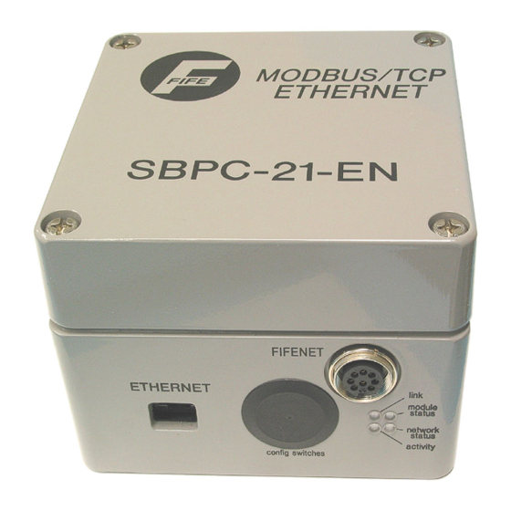
SBPC-21-EN External Connections/Indicators SBPC-21-EN mounting considerations are simplified as all connections to the SBPC-21-EN are on the same side of the box. Figure 1-3: SBPC-21-EN Side View Connection to FifeNet is accomplished using the standard FifeNet connector. Configuration is also downloaded to the device using this connection. -
Page 10: Sbpc-21-En Network Status
SBPC-21-EN Network Status The SBPC-21-EN network status is determined by interpretation of the external LED status as described in the table below. Figure 1-4: SBPC-21-EN LED Indicators Table 1-1 LINK LED LED State Meaning Ethernet network not detected. Solid Green The SBPC-21-EN is connected to an Ethernet network. -
Page 11: Sbpc-21-En Error Codes
The display will go blank for a moment and the cycle repeats unless the SBPC-21-EN has been configured to attempt to restart after an error. If this is the case, the error will only cycle once. All state machine errors 5XX are considered nonfatal and only cycle once. Below are the error codes and their meanings. -
Page 12: Tcp/Ip Features
PC. Special Case IP Addresses Devices on an Ethernet network are not allowed to be configured to the following IP addresses; therefore, do not configure the SBPC-21-EN to use any of them. IP ADDRESS DESCRIPTION IP address where the first byte is zero 0.X.X.X... -
Page 13: Configuring Ip Address
RFC 1918. Using DHCP/BootP If the configuration switches are set to 0, the SBPC-21-EN will read the configuration stored in FLASH. If DHCP/BootP is enabled and a DHCP or BootP server is found, the IP address, subnet mask, and gateway are automatically configured by the DHCP/BootP server. -
Page 14: Using Address Resolution Protocol (Arp)
The arp -s command will store the IP and MAC addresses in the PC’s ARP table. When the ping command is executed, the PC sends this information to the SBPC-21-EN using the MAC address. The module detects that it was addressed with the correct MAC address and adopts the IP address sent by the PC. -
Page 15: File System
Full - Forces the module to operate only at full duplex Half - Forces the module to operate only at half duplex Using a standard FTP client, this file can be transferred from the SBPC-21-EN to a PC, edited, and sent back. -
Page 16: Telnet Support
TELNET Support Through a TELNET client, the user can access the SBPC-21-EN file system using a command line interface similar to MS DOS™. The following commands are supported by this utility. Table 1-3 GENERAL COMMANDS Command Description This command will display version information, serial number, and MAC ID of the version module. -
Page 17: Modbus Tcp
Modbus TCP The SBPC-21-EN conforms to Modicon Open Modbus/TCP Specification, Release 1.0 (March 29, 1999). The SBPC-21-EN provides complete Class 0 conformance, complete Class 1 conformance, and partial Class 2 conformance. The SBPC-21-EN can handle 8 simultaneous connections. The following table lists the Modbus functions supported by the SBPC-21-EN:... - Page 18 07-02-2004 Figure Sheet 1-849-C Page 12...
-
Page 19: Fife Net Theory
CDP-01 permitting a single time slice to carry 16 words or 64 words. Multiplexing works by inserting the specified data words in a sequential repeating cycle. The receiving SBPC-21-EN synchronizes with the multiplexed data to extract it. This method trades data update speed for higher data quantities (up to 64 words per time slice). -
Page 20: Fifenet Master
The FifeNet protocol uses the time slice architecture described previously for configurable network traffic. Without some synchronization, however, neither the SBPC-21-EN, nor the CDP-01, would know where the time slice boundaries were located. This would create problems when they are trying to send and receive data. -
Page 21: Sbpc-21-En Data Flow
This is accomplished by using a block of memory in the SBPC-21-EN to reassemble FifeNet time slice data and then when it is complete, transfer it to the Modbus/TCP buffers for transmission on Modbus/TCP. - Page 22 07-02-2004 Figure Sheet 1-849-C Page 16...
-
Page 23: Configurations
• • • • • • Hardware Configuration – Single CDP-01 The SBPC-21-EN connection diagram is shown below. As you can see, this allows a single CDP-01 at FifeNet address 1 and an SBPC-21-EN at address 10. The SBPC-21-EN default Ethernet IP address is 192.168.0.1, but it can be changed using any of the methods described previously. -
Page 24: Hardware Configuration - Multiple Cdp-01'S
Hardware Configuration – Multiple CDP-01’s In the network below, the default SBPC-21-EN configuration is used multiple times to provide control to multiple CDP-01’s. Each SBPC-21-EN is connected to a single CDP-01 creating a separate FifeNet network for each CDP-01. Each SBPC-21-EN appears as both a FifeNet node and an Ethernet node. -
Page 25: Communication Mapping
SBPC-21-EN CUSTOMER INSTRUCTION MANUAL OMMUNICATION APPING • • • • • • Modbus to FifeNet Data In each of the three configurations (single-, dual-, or triple-drive CDP-01), the Modbus to FifeNet data is the same. The table below shows the configuration mapping for data traveling from Modbus to FifeNet. -
Page 26: Fifenet To Modbus Data
Panel Data 0 DWORD CDP-01 LED panel data. 0x4040-0x404F 0x404 Panel Data 1 0x4050-0x405F 0x405 WORD Device 1 Response CDP-01 Fife network responses. 0x4060-0x406F 0x406 Edge Left Sensor Value Sensor signal. 0x4070-0x407F 0x407 Edge Right Sensor Value Sensor signal. 0x4080-0x408F... - Page 27 Panel Data 0 DWORD CDP-01 LED panel data. 0x4040-0x404F 0x404 Panel Data 1 0x4050-0x405F 0x405 WORD Device 1 Response CDP-01 Fife network responses. 0x4060-0x406F 0x406 Edge Left Sensor Value Sensor signal. 0x4070-0x407F 0x407 Edge Right Sensor Value Sensor signal. 0x4080-0x408F...
- Page 28 Panel Data 0 DWORD CDP-01 LED panel data. 0x4040-0x404F 0x404 Panel Data 1 0x4050-0x405F 0x405 WORD Device 1 Response CDP-01 Fife network responses. 0x4060-0x406F 0x406 Edge Left Sensor Value Sensor signal. 0x4070-0x407F 0x407 Edge Right Sensor Value Sensor signal. 0x4080-0x408F...
-
Page 29: Control Information
The CDP-01 parallel input matrix is normally applied to the X7 port on the CDP-01. If the default matrix is using the SBPC-21-EN, the CDP-01 parallel input matrix is connected to a time slice. This connection allows serial commands to be used to control the CDP-01 instead of the hardware parallel input. -
Page 30: Dual-Drive Cdp-01
Dual-Drive CDP-01 CDP-01 Matrix: 100247-02X CDP-01 State Machine: 581000-020 SBPC-21-EN Matrix: 100411-02X CDP-01 Control Matrix Table 5-3 COMMAND VIA NETWORK DRIVE 1, AUTOMATIC DRIVE 1, MANUAL DRIVE 1, SERVO-CENTER DRIVE 1, JOG LEFT DRIVE 1, JOG RIGHT DRIVE 1, AUTO SETUP... -
Page 31: Triple-Drive Cdp-01
Triple-Drive CDP-01 CDP-01 Matrix: 100248-02X CDP-01 State Machine: 581000-020 SBPC-21-EN Matrix: 100412-02X CDP-01 Control Matrix Table 5-4 COMMAND VIA NETWORK DRIVE 1, AUTOMATIC DRIVE 1, MANUAL DRIVE 1, SERVO-CENTER DRIVE 1, JOG LEFT DRIVE 1, JOG RIGHT DRIVE 1, AUTO SETUP... -
Page 32: Status Data Block
Status Data Block For reference, the CDP-01 Status Data Blocks are listed in the tables on the following pages. NOTE: In the “Contacts” fields on the following tables: 0 = Low, 1 = High, Blank = Ignore Registers 0x403, 0x404: CDP-01 LED Panel Data PANEL DATA WORD 0: (0x403) PANEL DATA WORD 1: (0x404) Contact... - Page 33 Status Data Block (cont’d) Register 0x406: EDGE LEFT Sensor Value Register 0x407: EDGE RIGHT Sensor Value Register 0x408: LINE CENTER Sensor Value Register 0x409: LINE EDGE Sensor Value NOTE: These registers contain the normalized values of the connected sensors. Data Type: Signed 16-bit number. Range: -32768 to +32767 Register 0x40C: Common Status Register COMMON STATUS REGISTER: (0x40C)
- Page 34 Status Data Block (cont’d) Register 0x40D: Key Pressed To ensure proper recognition, a key must be depressed for a minimum of 500 ms. KEY PRESSED: (0x40D) Contacts 0x40D* (* = 0 - F) Hex Value 0x07FF 0xBFFF 0xDFFF 0xEFFF Sensor 0xF7FF Automatic 0xFBFF...
- Page 35 Status Data Block (cont’d) Registers 0x40E, 0x414, 0x41A: Drive-Specific Operating Mode. 0x40E – Drive 1, Contacts 0x40E0 through 0x40EF 0x414 – Drive 2, Contacts 0x4140 through 0x414F 0x41A – Drive 3, Contacts 0x41A0 through 0x41AF OPERATING MODE Contacts 0x40E*, 0x414*, 0x41A* (* = 0 - F) Description Automatic Servo-Center...
- Page 36 Status Data Block (cont’d) Register 0x410, 0x416, 0x41C: Drive-Specific Fault Register. 0x410 – Drive 1, Contacts 0x4100 through 0x410F 0x416 – Drive 2, Contacts 0x4160 through 0x416F 0x41C – Drive 3, Contacts 0x41C0 through 0x41CF FAULT REGISTER (SR0) Contacts 0x410*, 0x416*, 0x41C* (* = 0 - F) Description Fault –...
- Page 37 Status Data Block (cont’d) Register 0x412, 0x418, 0x41E: Drive-Specific Alarm Register. 0x412 – Drive 1, Contacts 0x4120 through 0x412F 0x418 – Drive 2, Contacts 0x4180 through 0x418F 0x41E – Drive 3, Contacts 0x41E0 through 0x41EF ALARM REGISTER (SR3) Contacts 0x412*, 0x418*, 0x41E* (* = 0 - F) Description Encoder –...
- Page 38 07-02-2004 Figure Sheet 1-849-C Page 32...
-
Page 39: Special Control Of Fife Net Devices
By skipping steps 1 and 2 in the sequence above and injecting key codes/commands into the command stream for the CDP-01, the SBPC-21-EN can simulate keys being pressed on its local panel. This provides the ability to make a fully functional remote control over the network. -
Page 40: Cdp-01 Key Codes
CDP-01 Key Code The CDP-01 keypad is shown below, along with the key codes for each key. The key codes can be used to send a command to the CDP-01 to simulate a key pressed on the CDP-01 keypad. Commands are sent via a 16 bit command word, Register 0 in Table 4-1. Commands are issued by placing an 8-bit “command”... -
Page 41: Cdp-01 Led Panel Data
CDP-01 LED Panel Data To make remote control complete, we must have a way to duplicate the CDP-01 panel LED’s. The CDP-01 keypad contains integrated LED’s to indicate operating modes, sensors selected, and many other parameters. The CDP-01 can be configured to send its panel LED data over FifeNet so that remote devices can duplicate the CDP-01 panel state. - Page 42 07-02-2004 Figure Sheet 1-849-C Page 36...
-
Page 43: Index
SBPC-21-EN CUSTOMER INSTRUCTION MANUAL NDEX • • • • • • Address Data Flow ............15 Ethernet............6 Data Mapping..........15 FifeNet............2 Data Transfer ..........15 ARP ..............7 DHCP ...............7 BOOTP ............7 Dip Switch CDP-01 IP Address ............3 Commands........... 33, 34 Settings............6... - Page 44 Producer/Consumer Model......1 0x0418, Drive 2 Alarm Register....31 Registers 0x0419, Drive 2 Encoder Value....31 0x0403, CDP-01 Panel Data Word 0 ..26 0x041A, Drive 3 Operating Mode ....29 0x0404, CDP-01 Panel Data Word 1 ..26 0x041B, Drive 3 Sensor Selection....29 0x0405, Device 1 Response ......
Need help?
Do you have a question about the SBPC-21-EN and is the answer not in the manual?
Questions and answers