Table of Contents
Advertisement
Becker Avionics GmbH • Baden-Airpark B108 • 77836 Rheinmünster • Germany
+49 (0) 7229 / 305-0 • Fax +49 (0) 7229 / 305-217
http://www.becker-avionics.com • E-mail: info@becker-avionics.com
Remote Controlled
Transponder
Mode S Level 2es
BXP6402
BXP6402-1R-(XX) Class 1
BXP6402-2R-(XX) Class 2
Software Versions:
upwards from Software Version
DSP:
SCI1026S305
FPGA: SCI1039S305
Installation and Operation
Manual
DV69802.03
Issue 04
June 2018
Article-No. 0584.071-071
Version 47
Version 55
Advertisement
Table of Contents

Related Manuals for Becker BXP6402-1R-01

Summary of Contents for Becker BXP6402-1R-01
- Page 1 Version 55 Installation and Operation Manual DV69802.03 Issue 04 June 2018 Article-No. 0584.071-071 Becker Avionics GmbH • Baden-Airpark B108 • 77836 Rheinmünster • Germany +49 (0) 7229 / 305-0 • Fax +49 (0) 7229 / 305-217 http://www.becker-avionics.com • E-mail: info@becker-avionics.com...
- Page 2 Becker Avionics GmbH have to be observed. To the extent that Becker Avionics GmbH provide component or system options based upon data or specifications provided by the user, the user is responsible for determining that such data and specifications are suitable and sufficient for all applications and reasonably foreseeable uses of the components or systems.
- Page 3 Installation and Operation Preface Dear Customer, Thank you for purchasing a Becker Avionics product. We are pleased that you have chosen our product and we are confident that it will meet your expectations. For development and manufacturing of our product, the guidelines for highest quality and reliability have been borne in mind, supplemented by selection of high quality material, responsible production and testing in accordance to the corresponding standards.
- Page 4 Page No.: Description Chapter Changed: Editorial adjustments. Added: Address box, User responsibility. Introduction Updated: User information. 2.4.3 Changed: Dimension drawing AM6400. 2.5.12 Updated: GPS Configuration. © by Becker Avionics GmbH / all rights reserved BXP6402 DV69802.03 Issue 04 June 2018...
-
Page 5: Table Of Contents
Installation and Operation Table of Contents General Description ........................11 1.1. Introduction..........................12 1.2. Purpose of Equipment ......................... 13 1.3. Variants Overview ........................14 1.3.1. Software Status ......................... 14 1.4. Safety-Conscious Utilization ....................... 15 1.5. Restriction for Use ........................15 1.6. - Page 6 Installation and Operation 2.8.3. BXP6402 with Serial Encoding Altimeter (Cutout) ............43 2.8.4. BXP6402 with RS232 GPS Receiver (Cutout) ..............43 2.9. Check after Installation ........................ 44 2.9.1. Pre-Flight Check Using Self-Test ..................44 2.9.2. Check of the Address Module ................... 44 2.9.3.
- Page 7 Installation and Operation List of Abbreviations List of Abbreviations Aircraft Address (24-bit ICAO) ACAS Airborne Collision Avoidance System Analog/Digital ADLP Avionics Data Link Processor Comm-A Definition Subfield ADS-B Automatic Dependent Surveillance-Broadcast Aircraft Identifier AICB Air Initiated Comm-B Altitude or Transponder ALT Mode Address Module ARINC Aeronautical Radio Incorporated...
- Page 8 Installation and Operation List of Abbreviations GICB Ground Initiated Comm-B Ground Global Positioning System IBIT Initiated Built-In Test Integrated Circuit ICAO International Civil Aviation Organization Identifier Ident (Identification) Instrument Flight Rules Input and/or Output Level 2es Surveillance with Comm A/B capability (transmitting and receiving with data block up to 112 bit).
- Page 9 Installation and Operation Units Units Ampere Milliampere °C Degree Celsius Centimetre Power Ratio In Decibel referenced to 1 mW Decibel Gram Kilogram Hertz Kilohertz Megahertz Millimetre Nautical Mile Ohm (Ω) Resistance Second Volt Millivolt Watt " Inch General Safety Definitions Indicates a hazardous situation which, if not avoided, will result in death or serious injury.
- Page 10 Installation and Operation Disposal The packaging material is inflammable, if it is disposed of improperly by burning, toxic fumes may develop. This product contains materials that fall under the special disposal regulation, which corresponds to the EC directive for dangerous disposal material. We recommend disposing of the respective materials in accordance with the respectively valid environmental laws.
-
Page 11: General Description
General Description Introduction General Description In this chapter you can read about: 1.1. Introduction..........................12 1.2. Purpose of Equipment ......................... 13 1.3. Variants Overview ........................14 1.3.1. Software Status ......................... 14 1.4. Safety-Conscious Utilization ....................... 15 1.5. Restriction for Use ........................15 1.6. -
Page 12: Introduction
General Description Introduction 1.1. Introduction This manual describes the installation and operation of the Mode S transponder BXP6402-XR-(XX). The ID label on your device shows the part number for identification purposes (see "Type Plate", page 25). Before starting operation of the unit(s) please read this manual carefully, with particular attention to the description referring to your device(s). -
Page 13: Purpose Of Equipment
• Mode C - in this mode, the encoded altitude is sent in addition to the mode A reply. The altitude information must be delivered from an external device (e.g. Becker Blind Encoder BE6400). •... -
Page 14: Variants Overview
General Description Variants Overview 1.3. Variants Overview Within the part number, the meaning of "-XR-(XX) " is: BXP 6402 - X R - ( X X ) Identifier Model Number Options 01= Standard XPDR Class 1= Class 1 2= Class 2 Design R= Remote Controlled 1.3.1. -
Page 15: Safety-Conscious Utilization
General Description Safety-Conscious Utilization 1.4. Safety-Conscious Utilization For safe operation of the product the following notes have to be observed: • The installation of the Mode S transponder into an aircraft may be carried out only by an authorized installation company. The country regulations always have to be observed. -
Page 16: Technical Data
General Description Technical Data 1.6. Technical Data 1.6.1. Electrical Characteristics BXP6402 Specifications Power supply 10...33 VDC Typical consumption 50 Mode S replies/s + Squitter 0.35 A at 14 V 0.20 A at 28 V in standby Mode: 0.18 A at 14 V 0.13 A at 28 V Serial interfaces RS422... -
Page 17: Transmitter Data
General Description Technical Data 1.6.2. Transmitter Data BXP6402 (Transmitter Data) Specifications Transmit frequency 1090 MHz ± 1 MHz Transmit modulation 12MOM1D PAM (Pulse Amplitude Modulation) Transmitter type Solid state ≥ 125 W (+21 dBW) at antenna end terminal and Transmit power (class 1) ≥... -
Page 18: Receiver Data
General Description Technical Data 1.6.3. Receiver Data BXP6402 (Receiver Data) Specifications Operating modes Mode A/C/S, depending on interrogation Receive frequency 1030 MHz ± 0.1 MHz (mode A/C) 1030 MHz ± 0.01 MHz (mode S) Sensitivity (MTL) -74 dBm ± 3 dB (for 90% reply rate in mode A/C and 99% in mode S) Selectivity ±15 MHz >... -
Page 19: Environmental Condition
General Description Technical Data 1.6.6. Environmental Condition BXP6402-XR-(XX) was tested in accordance with EUROCAE/RTCA ED-14D/DO-160D under consideration of below listed environmental categories and conditions: Characteristics Section Cat. Condition Temperature and Altitude Equipment tested to Category D1 Low Ground Survival Temperature 4.5.1 -55 C Low Operating Temperature... -
Page 20: Certifications
General Description Technical Data 1.6.7. Certifications Conformity BXP6402-XR-(XX) EASA.21O.322 ETSO-2C112a, class 1 or 2 TSO-C112, class 2A or 2B RTCA DO-181C EUROCAE ED-73B, Level 2es Software EUROCAE/RTCA ED12B/DO-178B Level C In accordance with: EURO CAE/RTCA ED-14D/DO-160D Operating altitude 50 000 ft. max. (class 1) 15 000 ft. -
Page 21: Order Code
General Description Order Code 1.7. Order Code 1.7.1. BXP6402 Mode S Transponder (remote controlled) BXP6402-1R-(01), class 1 Article-No. 0588.695-915 BXP6402-2R-(01), class 2 Article-No. 0588.717-915 1.7.2. Accessories Control unit for BXP6402 CU6401-1-(01) Article-No. 0572.896-915 Address module AM6400-1-(01) Article-No. 0572.942-915 Programming kit for Address module AMP6400-1, parallel interface Article-No. - Page 22 General Description Order Code Cable, connectors, ... 1K046 Cable harness, length 1 m Article-No. 0604.615-276 1SK504 BNC connector for cable RG58U, soldering Article-No. 0725.706-277 1SK503 TNC connector for cable RG58U, soldering Article-No. 0725.900-277 TNC coaxial connector for RG-58C/U, crimp Article-No. 0551.694-277 TNC coaxial connector for RG-223/U, crimp Article-No.
-
Page 23: Installation
Installation Order Code Installation This manual must be available close to the device during the performance of all tasks. Careful planning should be applied to achieve the desired performance and reliability from the product. Any deviations from the installation instructions prescribed in this document are under own responsibility. -
Page 24: Packaging, Transport, Storage
Installation Packaging, Transport, Storage 2.1. Packaging, Transport, Storage Visually inspect the package contents for signs of transport damage. 2.1.1. Packaging Material and Transport The packaging material is inflammable, if it is disposed of improperly by burning, toxic fumes may develop. The packaging material can be kept and reused in the case of a return shipment. -
Page 25: Type Plate
Installation Device Assignment 2.2.3. Type Plate The device type is defined by the type plate (on the housing): Example: Figure 1: Type Plate (example) Explanation: Example Type designation: BXP6402-1R-(01) BXP6402 = Transponder, BXP640X family Options: -1R-: class 1, remote controlled -2R-: class 2, remote controlled (01): standard Unique number of the particular device... -
Page 26: Mounting Requirements
Push the security-plate into the locking slot and tighten the securing-plate. • Carry out removal of the transponder in reversed order. 2.3.2. Blind Encoder (BE6400) For installation of the Becker Avionics Blind Encoder BE6400 the corresponding manual has to be noticed (BE6400 I&O manual Article-No. 0594.547-071). •... -
Page 27: Dimensions
Installation Dimensions 2.4. Dimensions 2.4.1. Transponder BXP6402-XR-(XX) Dimensions mm (inch) access to TX frequency adjustment Figure 2: Transponder BXP6402-XR-(XX) "Center of Gravity" without address module. Allowable deviation for dimensions without tolerances: DIN ISO 2768 T1 C xx...6 (±0.3) >30...120 (±0.8) >400...1000 (±2.0) >6...30 (±0.5) >120...400 (±1.2) -
Page 28: Transponder Bxp6402-Xr-(Xx) With Mounting Kit Mk4401
Installation Dimensions 2.4.2. Transponder BXP6402-XR-(XX) with Mounting Kit MK4401 Dimensions mm (inch) Figure 3: Mounting Kit MK4401 "Center of Gravity" without address module. Allowable deviation for dimensions without tolerances: DIN ISO 2768 T1 C xx...6 (±0.3) >30...120 (±0.8) >400...1000 (±2.0) >6...30 (±0.5) >120...400 (±1.2) >1000...2000 (±3.0) -
Page 29: Address Module Am6400-1-(01)
Installation Dimensions 2.4.3. Address Module AM6400-1-(01) Dimensions mm (inch) 46.4 (1.83 in) Figure 4: Address Module AM6400-1-(01) 2.4.4. Blind Encoder BE6400 Dimensions mm (inch) Figure 5: Blind Encoder BE6400 DV69802.03 Issue 04 June 2018 BXP6402... -
Page 30: Antenna 1A032
Installation Dimensions 2.4.5. Antenna 1A032 Dimensions mm (inch) Figure 6: Antenna 1A032 BXP6402 DV69802.03 Issue 04 June 2018... -
Page 31: Electrical Installation
Installation Electrical Installation 2.5. Electrical Installation • The installation of the Mode S transponder into an aircraft may be carried out only by an authorized installation company. The country regulations always have to be observed. Power supply: • Do not connect the unit to AC sources. •... -
Page 32: Bxp6402 Connector Layout
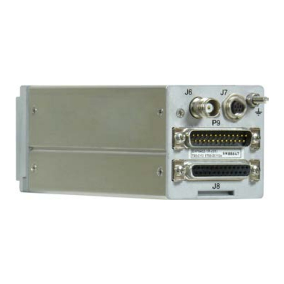
Installation Electrical Installation 2.5.2. BXP6402 Connector Layout J6: Antenna J7: Address module Figure 7: BXP6402 Connector Layout 2.5.3. Connector J6 Antenna RF connector (from transponder via cable to antenna). • Type: TNC female. Antenna cable: low-loss 50 Ω cable, RG 58C/U or RG 223/U type. •... -
Page 33: Connector J8 (Dsub 25-Pol Female)
Installation Electrical Installation Pin name Function Source Destination Recommended cable type current protection SUPP Supply voltage input, DC supply voltage BXP6402 AWG20 external 5 A fuse for source 10...33 V current protection DC supply ground, DC supply voltage BXP6402 AWG20 additionally ground connected to Pin25... - Page 34 Installation Electrical Installation Pin name Function Source Destination Recommended cable type GPS receiver GPS receiver BXP6402 AWG26 shielded Not connected Not connected Not connected Reserved for SQ GND SWITCH "Weigth on wheel" Aircraft BXP6402 AWG26 sensor, active LOW ALTS- RS422 data interface Serial encoding BXP6402 AWG26 shielded...
-
Page 35: Connector J7 (5-Pol Female)
Installation Electrical Installation 2.5.6. Connector J7 (5-pol female) J7 Pin Pin name Function Source Destination Power supply BXP6402 AM6400 C_CLK Clock AM6400 BXP6402 Not connected Reserved C_DAT Data AM6400 BXP6402 Power supply return BXP6402 AM6400 2.5.7. External Suppression External suppression should be connected if another transponder or DME is installed in the aircraft. The suppression pulses may not be compatible with all models of DME. -
Page 36: Programming Of The Address Module
J8. The interface is marked with "TISRX" and "TISTX" in the aircraft wiring diagram (see page 40). • The related protocol is specified in the attachment document "Data Transfer Interface Protocol BXP640X-XX-(XX)". This manual is available at the Becker Product Support under Article-No. 0590.258-071. BXP6402 DV69802.03 Issue 04 June 2018... -
Page 37: Gps Configuration
Installation Electrical Installation 2.5.12. GPS Configuration • If a GPS receiver is used, connect “GPS_EN” to DC supply ground. BXP6402 “GPS_EN” J8 pin2 DC supply ground. • GPS receiver data line connection to BXP6402 see: “BXP6402 with Parallel Encoding Altimeter & GPS Receiver” page 41. “BXP6402 with Serial Encoding Altimeter &... -
Page 38: Remote Control
• BXP6402 is a remote-controlled transponder and needs an additional controlling device. Use the control unit CU6401 from Becker Avionics; a special designed control unit, which offers the complete set of control functions and indications. Use another device (e.g. FMS). -
Page 39: Settings After Installation
Information front panel see "Operating with CU6401 Controller", page 45 Select with button Select with rotary encoder Store button (STO) ALTM SELECT GARMIN / TRIMBLE store NORTHSTAR store UPS AT (BECKER BE6400) store UPS AT LORAN store MAGELLAN store SHADIN store ARNAV... -
Page 40: Warning And Failure Indications
Installation Warning and Failure Indications **Shall be disabled if no ADLP or similar device is connected. *** Default configuration: Dimming input none Brightness Altitude displayed in ALT mode AI in SBY AI in ON IIlumination characteristics max. range Code 0000 0000 Flight number eight blanks... -
Page 41: Bxp6402 With Parallel Encoding Altimeter & Gps Receiver
Installation Aircraft Wiring 2.8.1. BXP6402 with Parallel Encoding Altimeter & GPS Receiver 2xAWG20 3 A (5 A if ext. load is connected to P9 pin6) SUPP +10...33 VDC supply SUPP AWG26 ON_N ON_N 2xAWG26 shielded, twisted Control unit CU6401 2xAWG26 shielded, twisted 10xAWG24 Parallel encoding altimeter... -
Page 42: Bxp6402 With Serial Encoding Altimeter & Gps Receiver
Installation Aircraft Wiring 2.8.2. BXP6402 with Serial Encoding Altimeter & GPS Receiver 2xAWG20 3 A (5 A if ext. load is connected to P9 pin6) SUPP +10...33 VDC supply SUPP AWG26 ON_N ON_N 2xAWG26 shielded, twisted Control unit CU6401 2xAWG26 shielded, twisted 10xAWG24 AWG26 shielded EXT. -
Page 43: Bxp6402 With Serial Encoding Altimeter (Cutout)
Installation Aircraft Wiring 2.8.3. BXP6402 with Serial Encoding Altimeter (Cutout) Serial encoding altimeter ALTS- ALTS+ Figure 10: BXP6402 - Serial Encoding Altimeter Connection (not for BE6400) 2.8.4. BXP6402 with RS232 GPS Receiver (Cutout) GPS receiver GPS_EN Figure 11: BXP6402 - RS232 GPS Receiver Connection (not with BE6400) If the blind encoder BE6400 is directly connected to J8 it is not possible to connect a GPS receiver for ADSB-out function to J8. -
Page 44: Check After Installation
Installation Check after Installation 2.9. Check after Installation After the installation, check the transponder to ensure satisfactory operation of the unit. This should be done on the ground. Generally, this should not be used during flight. 2.9.1. Pre-Flight Check Using Self-Test 2.9.1.1. -
Page 45: Operating Instructions
BXP6402 is a remote-controlled transponder and needs an additional controlling device. For further information about Interface and protocol refer to the document "BXP6400 Extended Protocol" available at the Becker Product Support. 3.1.1. Device Assignment This manual is valid for the following devices: •... - Page 46 Operating Instructions Operating with OEM Controller Blank Page BXP6402 DV69802.03 Issue 04 June 2018...
- Page 47 Operating Instructions Operating with OEM Controller Blank Page DV69802.03 Issue 04 June 2018 BXP6402...
-
Page 48: Index
Installation ............. 23 We reserve the right to make technical changes. The data correspond to the current status at the time of printing. © by Becker Avionics GmbH / all rights reserved *** End of the Document *** BXP6402 DV69802.03 Issue 04 June 2018...
Need help?
Do you have a question about the BXP6402-1R-01 and is the answer not in the manual?
Questions and answers