Table of Contents
Advertisement
Advertisement
Table of Contents

Related Manuals for Peavey Invective 120


Summary of Contents for Peavey Invective 120
- Page 1 Invective™ 120 Amplifier Head Operating Manual www.peavey.com...
- Page 2 (2) I’utilisateur de I’appareil doit accepter tout brouillage radioélectrique subi, même si le brouillage est susceptible d’en compromettre le fonctionnement. Warning: Changes or modifications to the equipment not approved by Peavey Electronics Corp. can void the user’s authority to use the equipment.
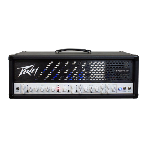
- Page 3 The new sound of metal is here. The Invective™ 120 is the culmination of nearly three decades of refinements and tweaks to Peavey’s legendary 6505 series with an all new clean channel and gobs of peripheral features that are staples for today’s developing musical styles. Designed in close conjunction with Misha Mansoor, of Periph- ery fame, the result is a monster of an amplifier capable of accurately reproducing tons and tons of the sickest tube amp tones imaginable….past, present, and future.
-
Page 4: Power Switch
FRONT PANEL CRUNCH MASTER PRE GAIN POST GAIN STANDBY POWER HIGH VOLUME LEAD NABLE ENABLE CLEAN GATE CRCH PRE GAIN LEAD INPUT HIGH POST THRESHOLD ENABLE ENABLE CHANNEL ENABLE ENABLE (1) POWER SWITCH Applies mains power to the unit. The red POWER STATUS LAMP (3) will illuminate when this switch is in the ON position. - Page 5 (6) POST GAIN This control, on the CRUNCH and LEAD channels, sets the overall level of its respective channel. (7) LOW, MID, and HIGH EQ These passive controls, on both the Crunch and Lead channels, provide the signature tone print of the Invective 120.
- Page 6 Each jack is capable of providing up to 500mA of current. (20 and 21) EFFECTS LOOPS These series loops are used to route the Invective 120 signal path through external effects devices or signal pro- cessors.
- Page 7 The “microphone” compensation very accurately reproduces the sound of whatever cab you are using in conjunction with the Invective 120. The LEVEL control adjusts the output level of the XLR jack, the TONE control adjusts the extreme high frequency response of the output to accommodate different high frequency drivers in PA systems, and the GROUND LIFT switch is used to break hum-inducing ground loops between the Invective 120 and outboard equipment.
-
Page 8: Top Panel
15 minutes. This should only be carried out by a technically competent person. (29) BIAS ADJUST Adjusting this will vary the bias supply. This should only be adjusted by a qualified Peavey technician, otherwise it could damage your tone, or worse, damage your power tubes. - Page 9 FOOTSWITCH (31) Remote Cable An eight-pin DIN connector is provided for connecting the footcontroller to the amplifier IN/FOOT (38) via the cable included in the carton. (32) Preset Mode Switches the footcontroller between NORMAL mode (default, LED off) and PRESET mode (LED red). Other LEDs will be red for Preset Mode, and green for Normal Mode.
-
Page 10: Using Preset Mode
(37) Drive Boost / Preset #5 NORMAL mode: This turns Drive BOOST on and off for the current channel. When switching between chan- nels, this will remember what the last setting was for each. The LED will be green when Drive BOOST is on. PRESET mode: This selects Preset 5. - Page 11 LINKING TO ANOTHER AMP AND/OR EFFECTS UNITS WITH THE MIDI OUT You can connect the MIDI Out to the MIDI In of another Invective 120 to synchronize the two amps. With the footswitch connected to the first amp, any changes you make with the footswitch (or front panel) will be dupli- cated on the 2nd amp –...
-
Page 12: Midi Implementation
MIDI IMPLEMENTATION This amp is designed to be extremely functional with the included 10-button footswitch. The 8-pin footswitch jack also works as a standard 5-pin MIDI input - to go along with the standard 5-pin MIDI output. There are times when the amp will be run with other types of MIDI foot controllers, a PC in the studio, or by an automated rack rig - or linked to another Invective via MIDI. - Page 13 MIDI PROGRAM MIDI Program Changes are used to recall presets. Typically a preset will reconfigure all functions on the amp at one time. (Programs 9-11 below are exceptions as they only affect the channel.) NOTE: These messages when recevied will be echoed to the MIDI Out jack for sync’ing with another Invective. NOTE: The first nine presets are your custom presets.
- Page 14 Factory Map: CHANNEL DRIVE BOOST MASTER BOOST GATE FX LOOP 1 FX LOOP 2 (decimal) (hex)
- Page 15 Factory Map: CHANNEL DRIVE BOOST MASTER BOOST GATE FX LOOP 1 FX LOOP 2 (decimal) (hex)
-
Page 16: Midi Sysex
MIDI SYSEX MIDI System Exclusive Commands are used to do all kinds of things that standard commands don’t handle. The Invective uses Sysex for things like backing up or restoring the 9 user presets, or transferring them to a 2nd amp. - Page 17 PRESET FORMAT NOTE: commands that send nibbleized preset data send HIGH byte/nibble, then LOW. Preset Bit: 15 14 13 12 2 1 0 Definition: gate gate effects loop 2, 1 n/a CTL 4 master boost 1 for chan 3 1 for chan 1 Overboost 1 = active / CTL 9...
-
Page 18: Specifications
SPECIFICATIONS Power Amplifier Section: Rated Power & Load: 120W(rms) into 16, 8, or 4 Ohms Power @ Clipping: (Typically @ 5% THD, 1kHz, 120VAC line) 130W(rms) into 16, 8, or 4 Ohms (Bias must be reduced to measure) Frequency Response: +0, -3dB, 50Hz to 20kHz, @ 100W(rms) into 8 Ohms Hum &... - Page 19 Effects Return: Impedance: Very High Z, 470K Ohms Designed Level: -10dBV, 300mV(rms) System Hum & Noise @ Nominal Level: (Clean Channel; 20Hz to 20kHz unweighted) Greater than 78dB below rated power Equalization: Custom Low, Mid & High passive type EQ Auxiliary Power Supply Jacks (x2): 9V DC (negative tip) @ 500mA Dimensions: 26.7”...
- Page 20 Warranty registration and information for U.S. customers available online at www.peavey.com/warranty or use the QR tag below Features and speci cations subject to change without notice. Peavey Electronics Corporation 5022 Hartley Peavey Drive Meridian, MS 39305 (601) 483-5365 FAX (601) 486-1278 Logo referenced in Directive 2002/96/EC Annex IV (OJ(L)37/38,13.02.03 and defined in EN 50419: 2005...