Table of Contents
Advertisement
Quick Links
"Streamline Closed Circuit"
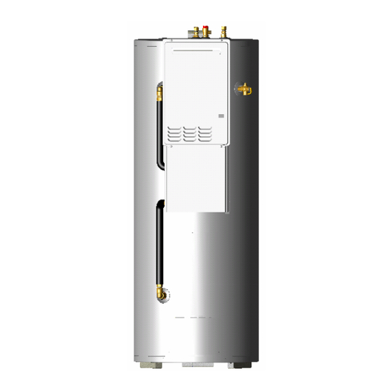
GAS BOOSTED
SOLAR WATER HEATER
OWNER'S MANUAL
AND
WARRANTY / INSTALLATION INFORMATION
WARNING: Plumber – Be Aware
Use copper pipe ONLY. Plastic pipe MUST NOT be used.
It is a requirement of a solar water heater installation that all
pipe work be in copper and not plastic, due to the effects of
high water temperatures.
Solahart Industries Pty Ltd
ABN 45 064 945 848
This water heater must be installed and serviced by an authorised person.
Please leave this guide with the householder.
Advertisement
Table of Contents

Related Manuals for Solahart GAS BOOSTED SOLAR WATER HEATER


Summary of Contents for Solahart GAS BOOSTED SOLAR WATER HEATER
- Page 1 WARNING: Plumber – Be Aware Use copper pipe ONLY. Plastic pipe MUST NOT be used. It is a requirement of a solar water heater installation that all pipe work be in copper and not plastic, due to the effects of high water temperatures.
- Page 2 DO NOT leave this guide inside of the cover of the water heater, as it may interfere with the safe operation of the water heater or ignite when the water heater is turned on.
-
Page 3: Table Of Contents
HOUSEHOLDER – We recommend you read pages 5 to 16. The other pages are intended for the installer but may be of interest. Introduction... 4 About Your Water Heater ... 5 How Your Water Heater Works... 10 Regular Care ... 12 Save A Service Call ... -
Page 4: Introduction
70 countries in Europe, North America, Africa and Asia. In our home market of Australia, we offer the widest range of thermosyphon solar water heater products, and we are now releasing the “STREAMLINE CLOSED CIRCUIT GAS BOOSTED” active solar hot water system. Our product is positioned within the hot water market as a reliable, durable product with state of the art manufacturing technology. -
Page 5: About Your Water Heater
This water heater has two outlets. One is a hot water outlet and the other is a tempered water outlet. The purpose of the hot water outlet is to deliver hot water at between 60°C and 75°C, usually for kitchen and laundry use. - Page 6 Propane model is unsafe and can cause damage to the water heater. TO TURN OFF THE WATER HEATER If you plan to be away from home for a few nights, we suggest you leave the water heater switched on. If it is necessary to turn off the water heater: •...
- Page 7 Open the gas isolation valve fully at the inlet to the water heater. • Plug in the water heater at the power outlet and switch on the electrical supply. The power outlet must be switched on for the solar controls to operate and solar gain to be achieved and for the gas booster to operate.
- Page 8 (refer to “Warranty Exclusions” on page 53). • If it is necessary to switch the power off to the water heater and there is a risk of freezing, then it is necessary to drain the gas booster (refer to •...
- Page 9 • When water stops flowing from the water heater, close the hot tap. Note: It is recommended not to screw the drain plugs back in, until the water heater is to be turned on again. “Turn Off The Water Heater”...
-
Page 10: How Your Water Heater Works
WATER OUTLET TEMPERATURE This water heater has two outlets. One is a hot water outlet and the other is a tempered water outlet. The purpose of the hot water outlet is to deliver hot water at between 60°C and 75°C, usually for kitchen and laundry use. - Page 11 GOING ON HOLIDAYS It is not necessary to switch off the electrical supply at the power outlet to the water heater if you are going away. However, if it is necessary to switch off the power to the water heater, refer to “To Turn Off...
-
Page 12: Regular Care
TEMPERATURE PRESSURE RELIEF VALVE This valve is near the top of the water heater and is essential for its safe operation. It is possible for the valve to release a little water through the drain line during each heating period. This occurs as the water is heated and expands by approximately 1/50 of its volume. -
Page 13: Save A Service Call
No flow of water from the hot tap may indicate a restriction in or failure of the cold water supply to the water heater. Check for water flow at other taps and that the cold water isolation valve (refer to page 29) is fully open. - Page 14 Running” on page 15). • Water heater size Do you have the correct size water heater for your requirements? The sizing guide in the sales literature and on the Solahart website needed. WATER FLOW FLUCTUATES More than one or two hot taps in use at the same time may cause a decrease in the hot water flow from the taps.
- Page 15 NEVER replace the relief valve with one of a higher pressure rating. • Heavy flows of hot water until the water heater is cold - then stops until water reheats The water heater must be switched off at the isolating switch or switchboard. Phone your nearest Solahart Dealer to arrange for an inspection.
- Page 16 ERROR CODE The water heater provides a diagnostic error code in the event of an interruption to its operation. The error code is displayed on the front of the water heater on the OK MONITOR. If an error code appears: •...
-
Page 17: Installation - Solar Storage Tank
Note: It is important for the solar storage tank to be orientated vertically upright in order for the falling film of closed circuit fluid to operate efficiently. A secondary flue is not required. The water heater must not be installed indoors or in a confined space. - Page 18 At least 500 mm between the gas booster and a fence, wall or other obstruction, in the direction of the flue discharge. The water heater can be turned through 90°, either to the left or to the right, with the discharge from the flue terminal discharging parallel to the wall. It is important the distance requirements from the Australian Gas Installations Standard AS 5601 are observed.
- Page 19 * Expansion control valve not supplied with the water heater. TANK WATER SUPPLY If the water heater is supplied with water from a tank supply, then a pressure pump system is recommended to ensure a minimum water pressure of 140 kPa is achieved to allow the gas booster to operate.
- Page 20 The section of roof and gutter should be isolated from the rainwater collection system before the commissioning of the solar water heater, so that any leak or spillage during commissioning does not make its way into the rainwater tank.
- Page 21 If a pressure limiting valve is installed on the cold water line to the water heater and the cold water line to another temperature limiting device branches off before this valve or from another cold water line in the premises, then a pressure limiting valve of an equal pressure setting may be required prior to the temperature limiting device.
- Page 22 CIRCULATED HOT WATER FLOW AND RETURN SYSTEM A solar water heater should not be installed as part of a circulated hot water flow and return system in a building. The benefits of solar gain will be significantly reduced and energy gained from the sun lost through the pipe work.
- Page 23 INSTALLATION – SOLAR STORAGE TANK REDUCING HEAT LOSSES The cold water line to and the tempered water and hot water lines from the water heater must be insulated in accordance with the requirements of AS/NZS 3500.4. The insulation must be weatherproof and UV resistant if exposed.
- Page 24 INSTALLATION – SOLAR STORAGE TANK DIMENSIONS AND TECHNICAL DATA Model DBV 270 Gas Booster Gas Booster Details Model Natural 271 026 NF Propane 271 026 PF Model numbers: N = Natural, P = Propane. Letter N or P is included in the model number, eg DBV 270 N5, to denote gas type.
- Page 25 INSTALLATION – SOLAR STORAGE TANK TYPICAL INSTALLATION – OUTDOOR LOCATION...
-
Page 26: Installation - Solar Collectors
INSTALLATION – SOLAR COLLECTORS SOLAR COLLECTOR LOCATION Consideration must be given to the position of the solar collectors in relation to the solar storage tank. There are limitations on both the maximum length of the solar hot and solar cold pipes and the maximum height between the solar storage tank and the solar collectors. - Page 27 INSTALLATION – SOLAR COLLECTORS PIPE LENGTHS The solar hot and solar cold pipes between the solar storage tank and the solar collectors shall: • be of DN15 hard drawn copper pipe. • have a continuous fall from the solar collectors to the solar storage tank of a minimum 5° (1 in 10 grade).
- Page 28 INSTALLATION – SOLAR COLLECTORS WARNING: Plumber – Be Aware • The solar hot and solar cold pipes between the solar storage tank and the solar collectors MUST BE of copper and fully insulated with closed cell polymer insulation or similar (minimum thickness 13 mm).
-
Page 29: Connections - Plumbing
It is necessary to remove the pipe cover from underneath the gas booster, by undoing the retaining screws, in order to make the water and gas connections to the water heater. Refit the pipe cover at the completion of the installation. - Page 30 Connect the drain line to the relief valve using a disconnection union. The pipe work from the relief valve to the drain should be as short as possible and fall all the way from the water heater with no restrictions. It should have no more than three right angle bends in it. Use DN15 pipe.
- Page 31 Local regulations may make it mandatory to install an expansion control valve (ECV) in the cold water line to the water heater. In other areas, an ECV is not required unless the saturation index is greater than +0.4 (refer to “Water Supplies”...
- Page 32 CONNECTIONS – PLUMBING To connect the solar cold and solar hot pipes to the solar storage tank: • Remove the compression nut and olive from each of the solar cold outlet and solar hot inlet fittings at the top of the solar storage tank. Remove the rubber washer from each of the unions and discard.
-
Page 33: Connections - Electrical
The water heater requires a 240 V AC, 50 Hz mains power supply for operation. The solar storage tank, supplied with a 1.8 metre power cord to operate the solar control unit and gas booster, requires a switched general purpose outlet (GPO) to be located within 1.2 metres of the installation. - Page 34 HOT SENSOR LEAD House the hot sensor lead at the water heater in the flexible conduit provided and secure the conduit in the cut out on the tab located behind the upper front cover. Connect the hot sensor cable to the hot sensor cable connector located on the tab behind the upper front cover.
-
Page 35: Commissioning
DO NOT leave this guide inside of the cover of the water heater, as it may interfere with the safe operation of the water heater or ignite when the water heater is turned on. - Page 36 • checking the level of the closed circuit fluid and adjusting if required. The water heater is supplied charged with closed circuit fluid. The level of the closed circuit fluid only needs to be checked if: •...
- Page 37 Warning: Although non-toxic, the following first aid advice and procedures should be followed if the closed circuit fluid concentrate comes into human contact or is spilt: • Swallowed - give milk or water and seek medical attention. • Eyes - wash with running water. •...
- Page 38 Commissioning the Solar Circuit To commission and check the solar circuit: Switch off the electrical supply at the power outlet to the solar storage tank. If the pump has been operating, wait five minutes to allow the drain back of the closed circuit fluid in the solar circuit.
- Page 39 Open the heat exchanger drain valve and remove the plug from the end of the hose. The closed circuit fluid will flood the hose to the static level of the closed circuit fluid inside of the heat exchanger. Mark the static level of the closed circuit fluid on the side of the solar storage tank with a non permanent marker.
- Page 40 10. Check the closed circuit fluid is circulating around the solar circuit. To check circulation: Listen for the trickling sound of the closed circuit fluid returning into the heat exchanger by placing your ear against the side toward the top of the solar storage tank. If the fluid is circulating around the solar circuit, a trickling sound will be heard as the fluid returns back into the heat exchanger.
- Page 41 Drain Back Function 13. Switch off the electrical supply at the power outlet to the solar storage tank. The pump will deactivate. The closed circuit fluid will drain back down to the heat exchanger and the level of the closed circuit fluid in the clear hose will rise.
- Page 42 Closed Circuit Fluid Level 15. Measure the distance from the text marking “MINIMUM FLUID LEVEL WITH PUMP OPERATING” to the closed circuit fluid dynamic level marked on the side of the solar storage tank during step 11. The correct closed circuit fluid dynamic level for efficient operation of the system when the pump is operating is between the “MINIMUM FLUID LEVEL WITH PUMP OPERATING”...
- Page 43 16. Determine the correct amount of water to be added to or closed circuit fluid to be drained from the heat exchanger if the dynamic level is either below the text marking “MINIMUM FLUID LEVEL WITH PUMP OPERATING” or more than 150 mm above this mark. Each 100 mm of fluid level height is equivalent to three (3) litres of closed circuit fluid.
- Page 44 17. Add water to top up the level of the closed circuit fluid in the heat exchanger if required. To add water to the closed circuit fluid: If not already removed, disconnect the drain line and remove the spring clip from the solar circuit relief valve at the top of the solar storage tank and remove the valve Warning: The solar circuit may be under pressure.
- Page 45 Pressure Testing the Solar Circuit 20. Close the heat exchanger drain valve. 21. Refit the solar circuit relief valve, orientating the valve outlet to the rear of the solar storage tank. Secure with the spring clip. Reconnect the drain pipe to the valve.
- Page 46 Remove Closed Circuit Fluid Level Hose 28. Remove the clear hose from the solar storage tank when satisfied the commissioning procedure is complete. To remove the hose: Ensure the heat exchanger drain valve is closed. Remove the hose from the side of the storage tank and place the end into a container to collect the closed circuit fluid remaining in the hose.
- Page 47 2 second interval between flashes. The green LED indicates the current operational mode of the solar water heater and the red LED indicates a fault mode. To view the status of the LEDs, it is necessary to remove the lower front cover.
- Page 48 Natural Gas If this minimum cannot be achieved, it may indicate the meter or the gas line to the water heater is undersized. It is important to ensure that an adequate gas supply pressure is available to the water heater when other gas burning appliances, on the same gas supply, are operating.
- Page 49 If the burners extinguish and / or an error code starts to flash on the display, release the MIN and adjuster buttons, close the hot tap, clear the error code, turn on the water heater and recommence the procedure from Step 1.
- Page 50 Damage caused by freezing due to the unavailability of power at the water heater is not covered by warranty (refer to been switched off to the water heater and there is a risk of freezing, then it is necessary to drain the gas booster (refer to “Draining the Water Heater”...
-
Page 51: Draining The Water Heater
Water will drain from the gas booster. • When water stops flowing from the gas booster, close the hot tap. Note: It is recommended not to screw the drain plugs back in, until the water heater is to be turned on again. Solar Storage Tank •... -
Page 52: Water Supplies
(TDS) content in the water is up to 2500 mg/L. In areas where the TDS exceeds 600 mg/L it is possible the black anode, which is the standard anode fitted to the water heater, may be excessively active. To alleviate this, the black anode should be replaced with one colour coded blue. -
Page 53: Warranty
Solahart Dealer from whom the water heater was purchased, the cost of transport, insurance and travelling costs 1. REPAIR AND REPLACEMENT WORK WILL BE CARRIED OUT AS SET OUT IN THE SOLAHART WATER HEATER WARRANTY, HOWEVER THE FOLLOWING EXCLUSIONS MAY CAUSE THE WATER HEATER WARRANTY TO BECOME VOID AND MAY INCUR A SERVICE CHARGE AND / OR COST OF PARTS. - Page 54 Receiver/Drier, Evaporator and associated pipe work. Solahart reserves the right to transfer fully functional components from the defective water heater to the replacement water heater if required. The term “water heater” used in the Warranty, Warranty Conditions and Warranty Exclusions means the Solahart supplied water heater(s), solar storage tank(s), solar collector(s), kit(s) and components.
- Page 55 (please circle) Booster Control (please circle) In-Line Booster Model No (if installed) Service’s Due If replacing a water heater, please give details Brand If a Solahart unit Tank Serial No Collector Serial No’s Comments Installer Certification – I certify this installation has been installed and tested in accordance with Solahart Industries Pty Ltd specifications...
-
Page 56: Solahart Offices
Corporate Headquarters 112 Pilbara St Welshpool Western Australia 6106 Postal Address: PO Box 95 State Parcel Centre Welshpool WA 6986 Australian Offices Western Australia Phone: Facsimile: Queensland Phone: Facsimile: Victoria / Tasmania Phone: Facsimile International Offices Europe Phone International: Facsimile International: Phone International: Facsimile International: Revision Date: 2006 July...