Advertisement
Quick Links
Advertisement

Related Manuals for ODM TTK-720


Summary of Contents for ODM TTK-720
- Page 1 TTK 720 Wireless Industry Fiber Test Kit User Guide...
-
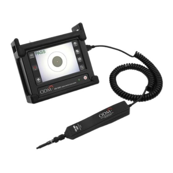
Page 2: Kit Overview
Introduction The TTK 720 test kit is an all-in-one solution for performing fiber inspection, insertion (dB) loss testing, and red laser continuity testing. This kit has been specifically designed to meet the needs of technicians working in the wireless communications field. Kit Overview Item Description... - Page 3 Kit Overview VIS 300C-PM-02-V* DLS 355 *VFL , OPM, and Scope included AC 4500 AC 602 AC 523 AC 107B AC 089 AC 040B AC 044B AC 092 AC 048B AC 049B Page 3 M-UM010-02 TTK 720 06/18...
- Page 4 TTK 720 kit. Some procedures may have more importance placed on them by the carrier: please use these procedures only as a guideline. Wireless carrier requirements supersede ODM’s recommended procedures in all circumstances. Proper Equipment Care Between Uses This section explains how to properly maintain the TTK 720 test kit components between uses.
- Page 5 Proper Equipment Care Between Uses 1a - Charging the VIS 300C The VIS 300C charger comes in two pieces. See diagram below. The cable on the right will be plugged into the power brick to create the charging device. Allow the VIS 300C to charge fully between uses. The VIS 300C can be used while charging; please be aware that an internal fan may activate to regulate temperature.
- Page 6 1b - Cleaning the DLS 355 The DLS 355 laser source is a high-end test laser, capable of outputting 1310 and 1550nm wavelengths. The output port of this unit utilizes a physical connection, which means that it can become soiled if used improperly. When needed, the DLS 355 adapter may be removed for inspection and cleaning of the fiber ferrule.
- Page 7 1d - Equipment Storage All equipment should be stored in the airtight case provided by ODM. Keep the case in a cool, dry location and remove battery from the DLS 355 if it must be stored for over 6 weeks.
- Page 8 Creating a New Folder in VIS 300C Software The VIS 300C platform saves all test information in a folder system onboard. The internal memory is capable of saving thousands of images and power meter readings. Follow the steps below to create a new folder when beginning a project.
- Page 9 The next screen contains several text fields which help make the project unique. Fill out these fields using the onscreen keyboard as appropriate, then touch “OK”. You’ll be taken back to the Main Inspection Screen. Enter all Project Details Touch “OK”...
- Page 10 61300-3-35. NOTE: SM UPC ≥45dB is by far the most common Touch fiber type used in Appropriate the wireless industry. IEC Profile Contact ODM if you are unsure of which algorithm to use. Page 10 M-UM010-02 TTK 720 06/18...
- Page 11 3b - Inspect the Fiber ODM’s automated analysis feature makes short work of fiber inspection. Follow these steps to determine if a fiber is acceptable for use. Insert the fiber ferrule into the inspection tip on the VIS 300C inspection probe as shown above. The ferrule should be inserted fully, until it “stops”...
- Page 12 Low Magnification High Magnification Once focused, the software will automatically center the fiber core onscreen. If a closer view of the live image is desired, touch the “+ Zoom” button in the bottom left corner of the screen. To go back to the original zoom level, touch the “- Zoom”...
- Page 13 3d - Run Automated Analysis When the fiber has been cleaned to the best of your ability (using dry and wet/dry methods), the image may be analyzed. Touch “Analyze” onscreen, press button on VIS 300C probe The software will run an automated analysis of the endface image and provide a PASS or FAIL designation.
- Page 14 3e - Save Image to Folder If the image needs to be saved for closeout reporting, follow these steps to save the image. Touch “Save” Touch the text line to bring up the keyboard ProjectName ProjectName Enter a name for the image.
- Page 15 dB Loss Testing Also known as “insertion loss” or “fiber sweep” testing, dB loss testing allows the technician to validate that all fiber pairs are in working condition. Saving of dB loss test results may be required for closeout packages. This section explains the necessary steps for testing fiber. 4a - Connect Test Jumpers for Referencing The equipment must be referenced before testing begins.
- Page 16 4b - Set Reference in VIS 300C Software When the test jumpers and loopback have been connected correctly, a reference must be set before testing can begin. Touch “Power Meter” onscreen -5.95dBm λ 1550nm The Power Meter screen interface will appear. All power meter testing (dB loss testing) will be done from this screen.
- Page 17 4c - Set PASS/FAIL Parameters Use the Settings menu to set PASS/FAIL parameters. Touch “Settings” 0.00dB λ 1550nm Touch each dark rectangle to set a MIN and MAX for testing. MIN should be set to zero. MAX allowable loss varies by build. Check your build documentation if you are not sure what to set for a MAX loss.
- Page 18 (and most basic) test scenario. Always conduct carrier build guidelines if unsure of the necessary procedures. Contact ODM if you encounter test scenarios or connector types that are unfamiliar. We have many accessory kits to match the requirements of major wireless carrier fiber architectures.
- Page 19 4e - Save Insertion Loss Readings When the test jumper and loopback are connected to the trunk fiber pairs, a live insertion loss value will be shown on the power meter screen. This number represents how much light is lost between the DLS 355 and VIS 300C OPM (up one side of the pair, through the loopback, and back down the other side of the pair.) 0.50dB λ...
- Page 20 4f - Edit Insertion Loss Readings If a reading is saved in error, or if a reading needs to be entered between two listed readings, it is possible to edit the list onscreen. Follow the instructions below to edit the list. 0.50dB λ...
- Page 21 VFL Testing An onboard red laser allows users to verify proper continuity of fiber cables. This is a troubleshooting task only. This section gives an overview of the VFL functionality. The VFL port on the VIS 300C has a 2.5mm universal output.
- Page 22 Creating and Sharing Reports The VIS 300C has built-in report creation software. This section explains how to create reports for closeout packages. 6a - Connect to Wi-Fi (Optional) If the reports will be shared via email or cloud storage, connect to a Wi-Fi network before continuing.
- Page 23 6b - Create Reports If the reports will be shared via email or cloud storage, connect to a Wi-Fi network before continuing. If you are not near a Wi-Fi network or will offload the reports via USB, skip this step. Touch “Projects”...
- Page 24 Touch the Share button on the Project Overview page to create closeout reports. You will be prompted to create new reports or overwrite existing reports. Touch “Share” to Begin Closeout Report Creation Images: 16 PM Readings: 8 If reports have never been created using the data in the project folder, a prompt will appear to create reports.
- Page 25 Email John Doe <John.Doe@odm-inc.com> If emailed, the reports will arrive in the recipient’s Inbox as HTML files. If you sent the files to yourself, simply double-click the file to open it in your preferred browser.
- Page 26 To offload results via USB, plug the VIS 300C into a computer using the included Micro USB cord. The Micro USB cord plugs in to the VIS 300C on the top panel, not in the port labeled “Probe Input” on the side panel.
- Page 27 Image Reports Image Reports will contain all images saved in the Project Folder, along with any information entered when the Project Folder was created. AR1A AR1B AR2A AR2B AR3A AR3B AR4A AR4B AR5A AR5B Power Meter Reports Power Meter Reports will contain all power meter readings saved in the Project Folder, along with any information entered when the Project Folder was created.
- Page 28 Sharing Closeout Reports from the Desktop The closeout reports can be shared as HTML files once they have arrived in your Inbox or cloud storage account. If you would prefer to save the results as PDF files, follow the instructions below. 1.
- Page 29 VIS 300C-PM-02-V Specifications Monitor/System Power Meter (Optional) Screen 5” Multi-touch LCD Wavelength Range 850nm to 1625nm Storage 8 GB (30,000 images) Calibrated Wavelengths 850/1310/1490/1550 Battery Lithium Ion -02: +6 to -60 dBm Measurement Range -04: +23 to -40 dBm Battery Life 4-5 hr continuous Resolution 0.01 dB...
-
Page 30: Warranty Information
Warranty Information All ODM equipment comes with a two-year warranty which extends from the date of purchase. The warranty covers defective material and/or poor workmanship only. The warranty does not cover devices which have been mishandled, destroyed, opened, or otherwise abused.
Need help?
Do you have a question about the TTK-720 and is the answer not in the manual?
Questions and answers