Table of Contents
Advertisement
Advertisement
Table of Contents

Related Manuals for Pentax G6


Summary of Contents for Pentax G6
- Page 2 User Manual TI Asahi Co.,Ltd Version 1.0...
-
Page 3: Table Of Contents
Front side of the Receiver..................6 1.2.2. Back side of the Receiver..................8 1.2.3. The bottom of Receiver..................8 Chapter2 Basic operations of G6....................10 The installation of base and rover ................10 The operation of keys....................11 Self-checking......................11 Measure the antenna height..................12 Chapter3 Web UI function......................21... -
Page 4: Chapter1 Brief Introduction
Chapter1 Brief introduction This chapter is mainly used to introduce the key features and the appearance of G6. As the latest generation of GNSS receiver, G6 brings you a better user experience. The dimension and weight also has a great breakthrough, now the dimension is diameter 131mm ×... - Page 5 (1) Compact and lightweight design. The dimensions of G6 is radius 131mm × height 102mm, but its weight is just 1kg (with battery). The compact and lightweight design allow users to carry out easily.
-
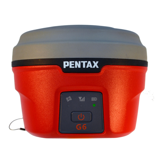
Page 6: G6 Receiver
1.2 G6 Receiver G6 receiver is a flat cylindrical, 102mm in height, 131mm in diameter. The front side has 1 power buttons and 3 indicators. The back side is a battery compartment. In the compartment, there are two slots, one for SIM card another for Micro SD card. - Page 7 Figure 1- 3 Network led power led (green and red) When you power on the G6, the power led will be on. According to the remaining power of the battery, it includes two kinds of status: 1. Green: power supply in good condition.
-
Page 8: Back Side Of The Receiver
1.2.2. Back side of the Receiver Figure 1- 5 G6 back side Number Name Function Battery compartment cover Protect the battery Compartment locker Open/lock the cover Micro SD card slot Put and read Micro SD card... - Page 9 Figure 1-6 G6 bottom Figure 1- 11 5-PIN interface Figure 1- 12 7-PIN interface Number Name Function Beeper Broadcast voice message Connect to external radio and external 5 pin interface battery USB port, also can connect to the 7 pin interface...
-
Page 10: Chapter2 Basic Operations Of G6
Chapter2 Basic operations of G6 In this section, we highlight the basic operations of G6. It includes the installation of bas and rover, the operation of keys, switching working mode and datalink, self-test. All of these basic operations are simple and easy. But they are very important. -
Page 11: The Operation Of Keys
Then you will listen beep for three times and the voice broadcast the current receiver status, it means the receiver powered on successful. Power off: when the G6 receiver is in the ON status (power supply light ON), ... -
Page 12: Measure The Antenna Height
2.4 Measure the antenna height When we use G6 collect static data or set G6 on a known point as a base station, the antenna height should be measured. Antenna height is actually the vertical height of the phase center to ground measurement point. But there are differences between different measure methods. - Page 13 Tips: 1. In order to make sure the accuracy, don’t replace battery during calibration 2. The pole should be set on the same point during all of the steps. (1) Horizontal Calibration Horizontal calibration is actually calibrating the E-bubble. Click “Adjust—Sensor Calibrate—Horizontal”.
- Page 14 Figure 2-2 Before celebration (left) after celebration (right) (2) Azimuth Calibration Click “Adjust—Sensor Calibrate—Azimuth”, then it will show the “Azimuth calibration” interface. Figure 2-3 As it shows in the interface, there are three steps to do, “Record Vertical, Record Horizontal, Calibrate”. Record vertical and horizontal data is order to get enough data to do the Azimuth Calibrate.
- Page 15 you finish a circle, the software will show the picture and have a beep sound. But sometimes, you had finished the circle and the software show the circle, software doesn’t transmit a beep sound and it doesn’t show “Record Horizontal” is successful.
- Page 16 Figure 2-5 The last step is “Calibrate”. After step one and two, it will show 2 circles on the screen. Then click “Calibrate”, it will calculate the parameter and ask you “Make sure using the parameter?” Click “Yes”, the parameter will be applied. Figure 2-6 (3) Declination Calibration After “Horizontal Calibration”...
- Page 17 Figure 2-8 (b) The second step is “Records Tilt”. In this step, you should collect tilt points in 4 direction, and in every direction you should collect 10 tilt points. There are some conditions to do this step. ① The pole should set on the same points during all of the steps when you are collecting tilt points.
- Page 18 Figure 2-9 Follow these four principles, then you can collect tilt points in four different directions. Each direction should has 10 points. As the picture shows, set the pole on one point, when you do this step. The tilt angle is 25°~30°, and make sure the receiver is stable to collect points.
- Page 19 Figure 2-12 West Figure 2-13 North After success record centers and tilts, then we should apply this parameter to project. Click “Correction” to calculate the parameters, if it exceed the limit, we should do the Sensor Calibrate again. If it doesn’t we can apply it. The software will give message on the screen.
- Page 20 Figure 2-14 Then all steps of Sensor Calibrate are finished. You can collect points with this function. It will make field work more convenient and reliable.
-
Page 21: Chapter3 Web Ui Function
Chapter3 Web UI function G6 has WIFI function, it could work as a hotspot, then Phone, controller, PC and other devices can connect its WIFI. The default WIFI name is device number, there is no password for this WIFI. After you power on the G6 receiver, you could search the hotspot via phone/PC/controller. -
Page 22: Status
The Web UI contains Status, Information, Download, Management, and Settings. It also can show the device number in the web. 3.1 Status In Status, you can see the current work status of the receiver, some basic information. Such as system mode, current datalink, coordinate, satellites, solution and so on. The detailed information you can see from the picture. -
Page 23: Download
Figure 3- 3 Information 3.3 Download “Download” is for downloading static data, you can download the datas you want to use, you also can package them together. The format of raw data is “.dat” version, if you want to use “.Rine” version, you can select. Figure 3- 4 Download 3.4 Management “Management”... -
Page 24: Device Register
Figure 3- 5 Management 3.4.1 Device register The register code is a 32 digits and letters, you could register the device via WEB UI function. The detailed steps as follow. In management page, you could see “registration”. Input register code to “Authcode” then click submit, the receiver will be registered. -
Page 25: Settings
Figure 3- 6 Registration You could also register device via controller. Connect G6 with the surpad software in controller. Click “About”, you will see “Register instrument”, then click it. The last step is inputting code, then finish registration. 3.5 Settings “Settings”... - Page 26 Figure 3- 7 Static mode Rover Mode In rover mode, you can select different datalink. Different datalink also has different options can be edited. The datalink includes UHF, Network, External and Bluetooth. If you select UHF mode, then you can select radio channel and radio protocol as you want.
- Page 27 Figure 3- 8 Rover mode (UHF datalink) If you select Network, then besides select satellites system and record raw data, the most important is that you can input CORS information, such as IP, account. Then get the mount point.
- Page 28 Figure 3- 9 Rover mode (Network datalink) If you select External, then it can connect to external radio. There is a very important thing, the external serial port band rate, this should be same with external radio.
- Page 29 Figure 3-10 Rover mode (External datalink) Then the last it’s Bluetooth, after selecting the datalink as Bluetooth, there are little option that you can configure, for example the cutoff angle, satellites system and record raw data. Figure 3- 11 Rover mode (Bluetooth datalink)
-
Page 30: Device Configuration
Base Mode Base mode also contains different datalink, most of the parameters are same. The only difference is the base mode has some more options can be edited, shows as follow. Others are same as rover. Figure 3- 12 Base mode 3.5.2. -
Page 31: Nmea Message
3.5.3. NMEA Message Here you can configure the NMEA message, turn on/ off them. If you need them out put, you also could select the update frequency. The NMEA contains GGA, GSA, GST, RMC, ZDA, GSV, VTG, GLL, GEDOP, GEREF, GESNR and GEVCV. Figure 3- 14 NMEA message... -
Page 32: Chapter4 G6 Standard Accessories
4.1 The case of G6 There are two kinds of G6 cases: Rover case and Base case. The inner layout of the base case and rover case is different. Base case has the room for external radio and rover case has the room for the controller. -
Page 33: Other Accessories
corresponding antennas have different length. The available range are: 410-430 MHz, 430-450 MHz and 450-470 MHz. They are suitable for field surveying, light and durable. The gain is 4 dBi. 410-430MHz 430-450MHz 450-470MHz Figure 4- 2 built-in radio antenna (not in scale) 4.4 Other accessories The other accessories are: 25cm supporting pole, bracket, connector between receiver and tribrach, and quick connector. -
Page 34: Appendix 1 Default Radio Configuration
Appendix 1 Default radio configuration The frequency and protocol of the 8 channels could be modified via Web UI or controller. So you could change it easily. And the Frequency range is from 410MHz to 470MHz, so you can elect as you want. Channel Frequency Protocol... -
Page 35: Specification
Error It will broadcast when the self-check failed. Self check It will broadcast when start self- check. GPS self check It will broadcast when self-check the GPS module. Radio self check It will broadcast when self-check the radio module. 3G self check It will broadcast when self-check the 3G module. - Page 36 Operating temp. - 30 ℃ + 65 ℃ Storage temp. - 40 ℃ + 75 ℃ Protection class IP67 Radio Modem Built-in Radio power Data format RTCM 、 NMEA RTK Initiation Reliability 99.99% Handheld Operating system Windows mobile 6.5 Operating software Surpad 3.0 Accuracy Horizontal...
Need help?
Do you have a question about the G6 and is the answer not in the manual?
Questions and answers