Table of Contents
Advertisement
Quick Links
Quick Start Guide (Cross-brand HSS)
Wireless
Flash
Transceiver
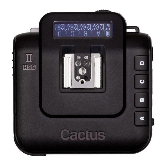
V6 II
Cautions and Warnings
Before using your V6 II, read the following safety
precautions to ensure correct and safe use:
• Turn OFF all your equipment (e.g. , Cactus units,
flash units, cameras, etc. ) before changing
batteries. Observe the correct polarity when
changing batteries. There is a danger of
explosion if the batteries are installed
incorrectly .
• Switch off the transceiver and remove batteries
during storage.
• Do not disassemble.
• Do not crush the V6 II and do not expose it to
any shock or force such as hammering, dropping,
or stepping on it.
Major Specifications
• Pre-installed f i rmware: supports cross-brand HSS
• Working radio frequency: 2. 4GHz
• Number of channels: 16
• Number of groups: 4
• Supports sync speed up to 1/8,000 second
• AF Assist LED: 1W
• Maximum effective distance: 100 meters
• Operating temperature: -20°C to +50°C
• Camera voltage handling: up to 6V
• Flash voltage handling: up to 300V
• Dimensions: 79mm (L) x 77mm (W) x 48 mm (H)
• Weight: 96g
• Power input: 2 x AA battery , 3V , 50mA, 0.15W; mini
USB 2.0, DC input 5V
Package Contents
V6 II Transceiver
Flash Stand FS-2
Camera and Flash Compatibility
Camera System Compatible Flash System
*
*
Fujif i lm flashes do not support HSS capabilities.
Nomenclature
TEST BUTTON/
SHUTTER RELEASE
BUTTON
AF ASSIST
LIGHT
LCD Panel
TX Mode
BATTERy INDICATOR
CHANNEL
SyNC MODE
INDICATOR
Installing the Batteries
Open the battery door
by pushing it backward.
Choose the Operation Mode
Set the V6 II transceiver to
Quick Start Guide,
the correct mode (transmitter
Sticker & Album
to "TX" , receiver to "RX") by
sliding the mode switch to the
correct position.
Setting the Channel
Set all of your V6 II transceivers to the same
channel (e.g. , channel 10) :
<RADIO SETUP>
RF60/RF60X
MULTI-SySTEM
SHOE (FEMALE)
LCD DISPLAy
X-SyNC PORT
MINI USB PORT
GROUP BUTTONS
MODE SWITCH
GROUP
POWER LEVEL
POWER LEVEL INCREMENT
MAIN SCREEN
POWER LEVEL/
FLASH
FLASH PROFILE
ZOOM
SySTEM
RELAy MODE
DELAy
CAMERA
INDICATOR
SySTEM
TIMER
StAtuS SCREEN (
+
)
Flip open the latch and
insert two AA batteries
using the correct
polarities. Then close
the battery door by
pushing it to the front.
<CHANNEL>
<10>
TRIPOD MOUNT
LANyARD
LOOP
BATTERy DOOR
LED STATUS INDICATOR
RX Mode
FLASH
PROFILE
BATTERy INDICATOR
CHANNEL
RELAy MODE
INDICATOR
Camera and Flash Indicators
Canon
Fujifilm
Nikon
Attaching to the Camera
LOCK
Turn the lock lever to
the RIGHT to LOCK the
multi-system shoe to
the camera.
Setting & Selecting the Group
• TX: Activate any
combination of groups
by pressing the group
buttons.
MULTI-SySTEM
SHOE (MALE)
HOT SHOE
LOCK LEVER
SELECTION DIAL
OK BUTTON
MENU BUTTON
POWER LEVEL
INCREMENT
POWER
FLASH
LEVEL
SySTEM
DELAy
WIRELESS
TIMER
SENSITIVITy
Olympus
Pentax
Others
(M43)
UNLOCK
Turn the lock lever to
the LEFT to UNLOCK the
multi-system shoe from
the camera.
• RX: Set each unit to
Group A, B, C, or D by
pressing the group
button. Each RX can
only be assigned to ONE
group.
Advertisement
Table of Contents

Related Manuals for Cactus V6 II


Summary of Contents for Cactus V6 II
-
Page 1: Cautions And Warnings
Before using your V6 II, read the following safety precautions to ensure correct and safe use: POWER LEVEL GROUP BATTERy INDICATOR INCREMENT FLASH POWER FLASH • Turn OFF all your equipment (e.g. , Cactus units, PROFILE LEVEL BATTERy INDICATOR SySTEM flash units, cameras, etc. ) before changing batteries. Observe the correct polarity when changing batteries. There is a danger of explosion if the batteries are installed incorrectly . - Page 2 2. Match the channel and the group of the TX and the RX. Forced HSS for Fujifilm V6 II Units Fujif i lm flashes do not support HSS flash exposure. However , Cactus V6 II offers a workaround to support Connection Handheld Mount on camera’s hot Connect to HSS flash with Fujif i lm cameras. shoe and connect using flash unit.
Need help?
Do you have a question about the V6 II and is the answer not in the manual?
Questions and answers