Advertisement
Quick Links
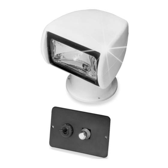
REMOTE CONTROL
SEARCH LIGHT
FEATURES
Constructed of noncorrosive ma te ri als
●
Sealed beam halogen lamp
●
Remote control and 15' cable in clud ed
●
●
Long life gear drive
Low amp draw
●
Patented clutch mechanism prevents motor damage
●
when running against limit stops
APPLICATION
Ideal for boaters...locate buoys, moorings, chan nel
markers, etc. Ideal for RV'ers...pin point road signs,
campsites, or use as backup light.
SPECIFICATIONS
320° horizontal movement
●
●
75° vertical sweep
50 watt 3-1/2" x 6" bulb
●
White thermoplastic housing and base
●
INSTALLATION INSTRUCTIONS
LIGHT MOUNTING
Select a location for the light which will allow for clear
beam projection forward and as far aft as pos sible.
Searchlight base should be mounted on level, flat
surface. Using the light base mounting template
enclosed, drill three (3) mounting holes and a center
hole at the center of base for wiring cable. Feed cable
through hole and fasten light in place with three (3) #10 x 1"
screws provided, or applicable screws for your particular
application. Mount light so that the Jabsco name on the
base is facing to the rear.
NOTE: SECURE CABLE WITH NYLON CLIPS OR
EQUIVA LENT. PROTECT INSTALLATION AT POINTS
OF STRESS, AND LEAVE ADEQUATE SLACK WHERE
CABLE MUST BE FLEXIBLE.
Model
Number
60020-0000
60020-0024
Voltage
Amps
12 Vdc
3.6
24 Vdc
2
Model 60020-Series 135 SL
Remote Control Unit
CONTROL INSTALLATION (60030-0000)
Select a location near the helm which will allow for
convenient operation of control.
1. Cut two holes (see Panel Cutout Template enclosed)
for mount ing control.
2. Route power leads (supplied by customer) from volt-
age source to control. Note: Wiring must be 16
gauge (mini mum).
3. Connect positive (+) power lead to red (+) wire and
negative (-) power lead to black wire using butt
connectors.
4. Connect wires (matching colors) from control panel
to end of light cable using butt connectors provided.
5. Use bedding compound or sealant to waterproof
control mounting.
6. Secure control with self-tapping screws provided.
Candlepower
100,000
100,000
Weights
Standard
lb (kg)
Carton
6 (2.7)
6 (2.7)
4
4
Advertisement

Subscribe to Our Youtube Channel
Related Manuals for JABSCO 60020-0000

Summary of Contents for JABSCO 60020-0000
- Page 1 2. Route power leads (supplied by customer) from volt- application. Mount light so that the Jabsco name on the age source to control. Note: Wiring must be 16 base is facing to the rear.
- Page 2 CONTROL UNIT OPERATION to match wire colors. Note: Install switch with yellow wire on top for correct di rec tional aiming. SWITCH FUNCTIONS 2. To remove On/Off fuse switch disconnect wires to (A) Light Switch – On/Off switch positions. defective switch and pull forward will gentle rocking (B) Directional Switch –...
- Page 3 DUAL STATION INSTALLATION KIT 43670-0005...
-
Page 4: Dimensional Drawing
1. Check voltage at power source. 2. Increase wire size from source to control. 3. Check for proper ground circuit. THE PRODUCTS DESCRIBED HEREIN ARE SUBJECT TO THE JABSCO ONE YEAR LIMITED WARRANTY, WHICH IS AVAILABLE FOR YOUR INSPECTION UPON REQUEST. www.jabsco.com U.S.A. -
Page 5: Panel Cutout
PANEL CUTOUT (Control Panel)
Need help?
Do you have a question about the 60020-0000 and is the answer not in the manual?
Questions and answers