Advertisement
Quick Links
X620 Series Switch Quick Reference
Electrical Hazard: Only qualified personnel should perform
installation procedures.
Risques d'électrocution: Seul un personnel qualifié doit effectuerles
procédures d'installation.
For complete installation instructions see the Extreme Networks
Summit Family Hardware Installation Guide at:
www.extremenetworks.com/documentation
Hardware Components
The following figures display the front and rear panel ports, LEDs,
and hardware components on a typical Summit X620 switch. See
the Extreme Networks Summit Family Hardware Installation Guide
for component details.
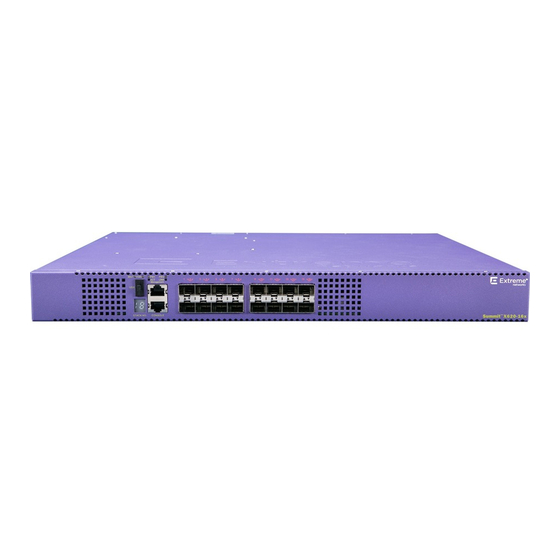
Figure 1
Summit X620 Sample Front Panel
1 Stack LED
4 100Mb/1Gb/10GBASE-X SFP+ ports
2 Console/Management ports
3 USB port
Figure 2
X620 Sample Rear Panel (Modular AC power)
1 Grounding Lug
3 Blank Panel
2 Fan Module
4 AC Power Supply
Figure 3
X620 Sample Rear Panel (Integrated AC power)
1 Grounding Lug
3 AC Power Socket
2 Redundant Power Input
Installation Site Requirements
The installation site must be within reach of the network cabling
and meet the requirements listed below:
• Appropriate grounded power receptacles must be located
within six feet of the site.
• A temperature of between 0°C (32°F) to 50°C (122°F) with
fluctuations of less than 10°C (18°F) per hour must be
maintained.
Caution: To ensure proper ventilation and prevent overheating,
leave a minimum clearance space of 7.6 cm (3.0 in.) on both sides
(front and rear) of the device.
Attention: Pour assurer une bonne ventilation et éviter une
surchauffe, laissez un espace de dégagement minimum de 7,6 cm
(3,0 po.) Des sur les deux côtés (avant et arrière) de l'appareil.
Warning: A readily accessible disconnect device shall be
incorporated in the building installation wiring.
Avertissement: Un dispositif de déconnexion facilement accessible
doit être incorporé dans l' installation électrique du bâtiment.
Handling the Switch
Caution: The switch can be damaged by electrostatic discharge.
To prevent electrostatic damage, attach an electrostatic discharge
(ESD) wrist strap to your wrist before handling the switch.
Unpack the switch as follows:
1 Remove the packing material protecting the switch.
2 Remove the tape seal on the non-conductive bag to remove the
switch.
3 Perform a visual inspection of the switch for any signs of
physical damage. Contact Extreme Networks if there are any
signs of damage. See
"Getting Help"
for more information on
contacting Extreme Networks.
Installing the Summit X620 Series Switch
You can install a Summit X620 Series switch in a rack. There are
four possible rack mounting configurations, depending upon
whether:
• The switch I/O ports or the power supply side of the device face
front
• The device is mounted flush with the rack posts or mid-mounted
Secure the X620 Series switches to the Rack
Caution: Before rack-mounting the device, ensure that the rack can
support it without compromising stability. Otherwise, personal
injury and/or equipment damage may result.
Note: The rack mounting brackets provide two holes for securing
the Summit X620 Series switches to the rack. Use two screws or
fasteners appropriate to your rack on each side when securing the
X620 Series switch to the rack.
To secure the Summit X620 Series switches to the rack:
1 Attach the mounting brackets to the sides of the switch using
six screws for each bracket.
2 Align the rack mount ear holes with the front rack post holes.
3 Secure the Summit X620 Series switches to each rack post with
two screws or fasteners appropriate to the rack.
Install Optical Transceivers
Warning: LASER RADIATION
Fiber-optic ports use Class 1 or Class 1M lasers.
DO NOT EXPOSE USERS OF TELESCOPIC OPTICS
Do not use optical instruments to view the laser output. The use of
optical instruments to view laser output increases eye hazard. Use
only UL/CSA, EN60825-1/-2 recognized pluggable modules.
Avertissements: RAYONNEMENT LASER
Ports de fibres optiques utilisent des lasers de classe 1 ou de
classe 1M .
NE PAS exposer les utilisateurs de télescopique OPTIQUE.
Ne pas utiliser d'instruments optiques pour voir la sortie du laser.
L'utilisation de instruments optiques pour afficher la sortie laser
augmente les risques oculaires. Utilisez uniquement UL / CSA,
EN60825-1 /-2 reconnu modules enfichables.
This installation procedure applies to all optical transceivers. To
install a transceiver in a Summit X620 Series switch:
1 Attach the anti-static wrist strap to your wrist and connect the
metal end to an appropriate ground point on the rack.
2 Remove the optical transceiver from the packaging.
3 If there is a protective dust cover on the connector, remove it at
this time.
4 Hold the optical transceiver so that the connector will seat
properly.
5 Carefully align the optical transceiver with the port slot.
6 Push the optical transceiver into the port slot until the
transceiver clicks and locks into place.
Connect Power to the Switch
Warning: Extreme Networks power supplies do not have switches
for turning the unit on and off. Disconnect all power cords to remove
power from the device. Make sure that these connections are easily
accessible.
Warning: A dedicated Listed circuit breaker rated at 15A is to be
used for each power supply connection.
Warning: Always make sure that the DC circuit is de-energized
before connecting or disconnecting DC power cables.
You can connect to a single, primary source of power, or to two
sources of power for redundancy.
Note: Installing the system as described in this guide meets the
protective earth grounding requirements of the National Electrical
Code (NEC) UL 60950 and IEC 60950 standards. However, in some
cases, it may be necessary to use an alternative grounding method.
In these cases, a 14 AWG wire can be connected between the
ground lug on the chassis and a nearby building ground point.
To power-up your X620 Series switch, do the following:
1 For AC powered units, connect the AC power cord to the AC
power input socket on the switch and an AC power outlet.
2 For DC powered switches, first verify the DC circuit is de-
energized and then do the following:
a Identify the grounding lug on the back of the switch. The
grounding lug is the middle screw of the power connector
panel, identified by the international symbol for earth ground.
b Connect the spade terminal end of the ground wire to the
grounding lug on the back of the switch with the M4x0.7
screw provided and the other end to a reliable earth ground.
Use stranded copper wire, minimum size 14 AWG maximum
size 6 AWG.
c Using a cross-head (Phillips) torque screwdriver, tighten the
retaining screw to 20 pound-inches (2.25 Newton-meters).
d Connect the DC power input cables to the DC input terminal
block on the rear of the switch.
e Energize the circuit.
3 If applicable, attach the cable from your redundant power
supply (RPS) into the X620 Series switch's redundant power
supply receptacle.
4 Once power is connected, verify that the PSU LED and RPS LED
(if applicable) turns green. If the PSU and RPS LEDs do not turn
green, refer to the Extreme Networks Summit Family Hardware
Installation Guide for troubleshooting information.
Selection of Power Cords
Extreme Networks does not include any power input cords. To
purchase the correct power cord for your specific country, refer to
www.extremenetworks.com/product/powercords/
for power cord
details to purchase a cord from Extreme Networks or your local
supplier.
Initial Network Connection and Configuration
Once you have connected power to the switch and verified LED
activity, complete the setup process as follows:
1 Connect a management station to the console port using either
an Ethernet to serial adapter or DB-9 serial cable
2 Verify that the system LEDs are on (solid green or blinking
green).
3 Using PuTTY, TeraTerm, or other terminal emulator, connect to
the switch using the serial port connection. Be sure that your
serial connection is set properly:
– 9600 baud
– 8 data bits
– 1 stop bit
4 Using the console session, perform the following:
a At the password prompt, press ENTER (RETURN) twice.
b Enter user: admin
c For the initial password, simply press ENTER.
d Follow the screen prompts for initial configuration.
e Enter the show version command. Record the switch serial
number. The following is example output with the serial
number in bold:
Transit.3 # show version
Switch : 800444-00-05 1208G-00882 Rev 5.0 BootROM:
5 Go to Extreme Networks e-support at
https://
esupport.extremenetworks.com
6 After logging in, go to the product registration page:
http://
extrwebapps.extremenetworks.com/Webapps/Public/
ProductReg/.
7 Enter the serial number of the switch.
8 Download the software to your pc from the software download
page at the esupport website:
https://
esupport.extremenetworks.com/eservice_enu/
start.swe?SWECmd=Login&SWEPL=1&SWETS=
9 Connect back to the switch via the console port and connect a
Ethernet cable to the management port on the switch to your
PC.
10 You might need to reset the IP address on your PC to some
address (for example, 10.10.10.10 255.255.255.0) to avoid
IP conflict.
11 At the switch, set the IP address of the switch (for example,
enter: con mgmt ipa 10.10.10.9/24).
12 Enter save config to save your configuration.
13 Start a TFTP session using a program such as TFTPD64. Point
the TFTP server to your PC IP address and EXOS image file
saved on your PC.
14 At the switch, download the new software to the switch
(example: download image 10.10.10.10 summitX-
15.4.1.3-patch1-9.xos).
15 Install the software after it loads by typing Y when prompted if
you want to install the load.
16 When the download and install finishes, instruct the switch to
reboot when prompted by entering: reboot.
Optional CLI Commands
Once logged into the switch you can create new VLANs by issuing
the following two commands:
•
create vlan <vlan name>
•
configure vlan <vlan name> tag XXXX
(replace XXXX
with the VLAN tag number - options are 1-4096)
These two commands will create a VLAN, give it a logical name,
and assign a tag number.
To configure a Default Gateway in the Extreme Networks CLI,
enter: configure iproute add default <IP Address>
Port Configuration CLI Commands
For additional port configuration CLI commands, refer to the
Extreme XOS Command Reference Guide at:
www.extremenetworks.com/documentation.
Specifications
Temperature and Humidity
Operating Temperature:
0°C (32°F) to 50°C (122°F)
Storage Temperature:
-40°C to 70°C (-40°F to 158°F)
Operating Relative Humidity:
10% to 95% (non-condensing)
Power Specifications
X620-16x
AC Input: - 100-240 V AC, 0.9A max. per PSU,
(Part # 17401)
50/60Hz
DC Input: +24V/-48V, 3.3A max. per PSU
X620-16t
AC Input: 100-240 V AC, 4.7A max. per PSU,
(Part # 17402)
50/60Hz
DC Input: +24V/-48V, 4.6A max. per PSU
X620-16p
AC Input: 100-240 V AC, 10A max. per PSU,
(Part # 17403)
50/60Hz
X620-10x
AC Input: 100-240 V AC, 0.5A max., 50/60Hz
(Part # 17404)
X620-8t-2x
AC Input: 100-240 V AC, 0.6A max., 50/60Hz
(Part # 17405)
Switch Dimensions
X620-16x
4.4 cm (1.73 in) H x 44.1 cm (17.38 in) W x 43.0 cm
(Part # 17401)
(16.94in) L Unpackaged Weight: 5.00 kg (11.02 lb)
X620-16t
4.4 cm (1.73 in) H x 44.1 cm (17.38 in) W x 43.0 cm
(Part # 17402)
(16.94in) L Unpackaged Weight: 5.10 Kg (11.24 lb)
X620-16p
4.4 cm (1.73 in) H x 44.1 cm (17.38 in) W x 43.0 cm
(Part # 17403)
(16.94in) L Unpackaged Weight: 5.40 Kg (11.90 lb)
X620-10x
4.4 cm (1.73 in) H x 30.5 cm (12.01 in) W x 26.1 cm
(Part # 17404)
(10.28 in) L Unpackaged Weight: 2.70 Kg (5.95 lb)
X620-8t-2x
4.4 cm (1.73 in) H x 30.5 cm (12.01 in) W x 26.1. cm
(Part # 17405)
(10.28 in) L
Unpackaged Weight: 2.80 Kg (6.17 lb)
Interfaces
Each Summit X620 Series switch has a USB, management, and
console port. The following table lists the specific interfaces for
each switch.
X620-16x
Summit X620 16 100Mb/1Gb/10GBASE-X SFP+
(Part # 17401)
ports, two unpopulated power supply slots, one
unpopulated fan module slot, ExtremeXOS Edge
license
X620-16t
Summit X620 12 100Mb/1Gb/10GBASE-T ports with
(Part # 17402)
EEE, four 100Mb/1Gb/10GBASE-T with EEE shared
with four 100Mb/1Gb/10GBASE-X SFP+ ports, two
unpopulated power supply slots, one unpopulated
fan module slot, ExtremeXOS Edge license
X620-16p
Summit X620 12 100Mb/1Gb/10GBASE-T PoE (eight
(Part # 17403)
PoE++ and four PoE+) and EEE, four 100Mb/1Gb/
10GBASE-T PoE+ and EEE shared with 4 100Mb/
1Gb/10GBASE-X SFP+ ports, two unpopulated
power supply slots, one unpopulated fan module
slot, ExtremeXOS Edge license
X620-10x
Summit X620 10 100Mb/1Gb/10GBASE-X SFP+
(Part # 17404)
ports, integrated power supply and fans,
ExtremeXOS Edge license
X620-8t-2x
Summit X620 eight 100Mb/1Gb/10GBASE-T with
(Part # 17405)
EEE, and two 1Gb/10GBASE-X SFP+ ports,
integrated power supply and fans, ExtremeXOS
Edge license
Advertisement

Related Manuals for Extreme Networks Summit X620-16x


Summary of Contents for Extreme Networks Summit X620-16x
- Page 1 Otherwise, personal The following figures display the front and rear panel ports, LEDs, details to purchase a cord from Extreme Networks or your local Power Specifications injury and/or equipment damage may result.
- Page 2 • 47 CFR Part 15, Class A when installed into Extreme products Legal Notices Korea EMC Statement (KCC) Extreme Networks, Inc., on behalf of or through its wholly-owned subsidiary, X620-16t Enterasys Networks, Inc., reserves the right to make changes in...