
Related Manuals for Measurement Computing USB-3103


Summary of Contents for Measurement Computing USB-3103
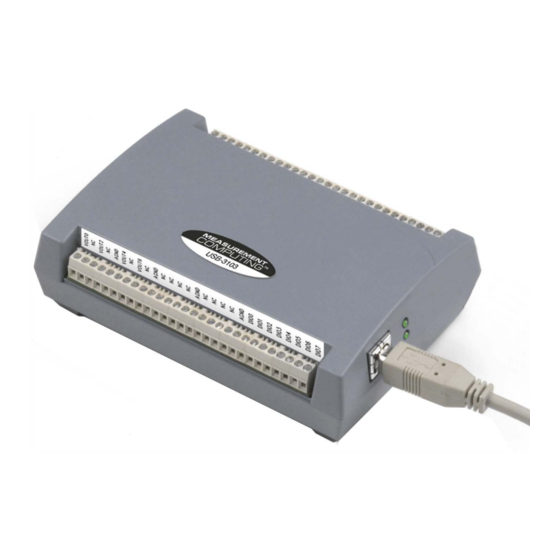
- Page 1 USB-3103 Eight analog voltage output (16-bit) Eight digital 1/0, one 32-bit event counter Full-speed USB 2.0 device User's Guide ..,,,. MEASUREMENT �y� •� COMPUTING™...
- Page 2 USB-3103 USB-based Analog Output User Guide Document Revision 3A, March, 2009 © Copyright 2009, Measurement Computing Corporation...
- Page 3 Other product and company names mentioned herein are trademarks or trade names of their respective companies. © 2009 Measurement Computing Corporation. All rights reserved. No part of this publication may be reproduced, stored in a retrieval system, or transmitted, in any form by any means, electronic, mechanical, by photocopying, recording, or otherwise without the prior written permission of Measurement Computing Corporation.
- Page 4 Information furnished by Measurement Computing Corporation is believed to be accurate and reliable. However, no responsibility is assumed by Measurement Computing Corporation neither for its use; nor for any infringements of patents or other rights of third parties, which may result from its use. No license is granted by implication or otherwise under any patent or copyrights of Measurement Computing Corporation.
-
Page 5: Table Of Contents
Overview: USB-3103 features ........................... 8 USB-3103 block diagram ........................... 9 Software features ..............................9 Chapter 2 Installing the USB-3103 ........................10 What comes with your USB-3103 shipment? ....................10 Hardware ..................................10 Additional documentation ..............................10 Unpacking the USB-3103..........................10 Installing the software ............................11 Installing the hardware ............................. - Page 6 USB-3103 User's Guide Mechanical ............................... 22 Main connector and pin out ..........................22 Declaration of Conformity ........................23...
-
Page 7: Preface
Preface About this User’s Guide What you will learn from this user's guide This user's guide describes the Measurement Computing CIO-DDA06/Jr/16 data acquisition board and lists hardware specifications. Conventions in this user's guide For more information Text presented in a box signifies additional information related to the subject matter. -
Page 8: Introducing The Usb-3103
Overview: USB-3103 features This user's guide contains all of the information you need to connect the USB-3103 to your computer and to the signals you want to control. The USB-3103 is part of the Measurement Computing brand of USB-based data acquisition products. -
Page 9: Usb-3103 Block Diagram
Microcontroller SYNCLD Event Counter 1 channel (32-bit) Figure 2. USB-3103 block diagram Software features For information on the features of InstaCal and the other software included with your USB-3103, refer to the www.mccdaq.com/PDFs/manuals/DAQ-Software-Quick-Start.pdf. Check www.mccdaq.com/download.htm for the latest software version. -
Page 10: Installing The Usb-3103
As with any electronic device, you should take care while handling to avoid damage from static electricity. Before removing the USB-3103 from its packaging, ground yourself using a wrist strap or by simply touching the computer chassis or other grounded object to eliminate any stored static charge. -
Page 11: Installing The Software
Connecting the USB-3103 to your system To connect the USB-3103 to your system, turn your computer on, and connect the USB cable to a USB port on your computer or to an external USB hub that is connected to your computer. The USB cable provides power and communication to the USB-3103. -
Page 12: Calibrating The Usb-3103
If the power LED turns off If the power LED is illuminated but then turns off, the computer has lost communication with the USB-3103. To restore communication, disconnect the USB cable from the computer, and then reconnect it. This should restore communication, and the power LED should turn back on. -
Page 13: Chapter 3 Functional Details
Status LED The Status LED indicates the communication status of the USB-3103. It flashes when data is being transferred, and is off when the USB-3103 is not communicating. This LED uses up to 10 mA of current and cannot be disabled. -
Page 14: Screw Terminal Banks
Screw terminal banks The USB-3103 has two rows of screw terminals—one row on the top edge of the housing, and one row on the bottom edge. Each row has 28 connections. Use 16 AWG to 30 AWG wire gauge when making screw terminal connections. -
Page 15: Analog Voltage Output Terminals (Vout0 To Vout7)
USB-3103 User's Guide Functional Details Figure 5. USB-3103 signal pin out Analog voltage output terminals (VOUT0 to VOUT7) The screw terminal pins labeled are voltage output terminals (see Figure 5). The voltage VOUT0 VOUT7 output range for each channel is software-programmable for either bipolar or unipolar. The bipolar range is ±10 V, and the unipolar range is 0 to 10 V. -
Page 16: Digital I/O Control Terminal (Dio Ctl) For Pull-Up/Down Configuration
Configure as an output (master mode) to send the internal D/A LOAD signal to the SYNCLD pin. You can use the SYNCLD pin to synchronize with a second USB-3103 and simultaneously update the DAC outputs on each device. Refer to Synchronizing multiple units on page 17. -
Page 17: Synchronizing Multiple Units
DAC outputs of both devices. Do the following. 1. Connect the SYNCLD pin of the master USB-3103 to the SYNCLD pin of the slave USB-3103. 2. Configure the SYNCLD pin on the slave device for input to receive the D/A LOAD signal from the master device. -
Page 18: Chapter 4 Specifications
100 Hz max., system dependent Multi-channel 100 Hz/#ch max., system dependent The USB-3103 output voltage level defaults to 0 V whenever the output voltage range is Note 1: reconfigured. The USB-3103 output voltage level will also default to 0 V: 1) Whenever the host PC is reset, shut down or suspended. -
Page 19: Analog Output Calibration
The maximum differential non-linearity specification applies to the entire 0 to 70 °C temperature range of the USB-3103. This specification also accounts for the maximum errors due to the software calibration algorithm (in Calibrated mode only) and the DAC8554 digital to analog converter non-linearities. -
Page 20: Synchronous Dac Load
USB-3103 User's Guide Specifications Pull up and pull down configuration area available using the DIO CTL terminal block pin 54. Note 4: The pull down configuration requires the DIO CTL pin (pin 54) to be connected to a DGND pin (pin 50, 53 or 55). -
Page 21: Memory
Available at terminal block pin 56 10 mA max. This is the total quiescent current requirement for the USB-3103 which includes up to 10 mA for Note 7: the status LED. This does not include any potential loading of the digital I/O bits, +5 V user terminal, or the VOUTx outputs. -
Page 22: Environmental
USB-3103 User's Guide Specifications Environmental Table 13. Environmental specifications Operating temperature range 0 to 70 °C Storage temperature range -40 to 85 °C Humidity 0 to 90% non-condensing Mechanical Table 14. Mechanical specifications Dimensions 127 mm (L) x 88.9 mm (W) x 35.56 (H) Main connector and pin out Table 15. -
Page 23: Declaration Of Conformity
Address: 10 Commerce Way Suite 1008 Norton, MA 02766 Measurement Computing Corporation declares under sole responsibility that the product USB-3103 to which this declaration relates is in conformity with the relevant provisions of the following standards or other documents: Category: Electrical equipment for measurement, control and laboratory use. - Page 24 Measurement Computing Corporation NI Hungary Kft 10 Commerce Way H-4031 Debrecen, Hátar út 1/A, Hungary Norton, Massachusetts 02766 Phone: +36 (52) 515400 (508) 946-5100 Fax: +36 (52) 515414 Fax: (508) 946-9500 http://hungary.ni.com/debrecen E-mail: info@mccdaq.com www.mccdaq.com...
Need help?
Do you have a question about the USB-3103 and is the answer not in the manual?
Questions and answers