Table of Contents
Advertisement
Quick Links
Alarm
Alarm Sound Pattern (Same pattern for temperature high
/ low and probe unplugged alarms)
1 second (beep, beep) -> silence for 5 seconds -> 1
second (beep, beep) -> silence for 5 seconds .....
Temperatures are updated during the silent 5 seconds.
Alarm keeps sounding until it is turned off by pressing the
"PASSWORD" button once. The function of the
"PASSWORD" button is just for stopping the alarm when
the alarm sounds.
Key Tone
The key tone will sound when a key is pressed for a valid
function.
Physical
• Battery cover removable with screwdriver only.
• Unit to be water splash resistant (IPX4).
• Velcro kit for mounting to outside unit.
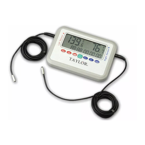
Thank you for purchasing a Taylor® Recording Thermometer
with dual probes. This product is an example of superior
design and craftsmanship. This product will the allow user to
record and monitor temperature and would be ideal for most
hospital environments. Please read this instruction manual
carefully before use. Keep these instructions handy for future
reference.
Description of Parts
14
1
3
2
Pass
SET
UP
DOWN
SET
UP
DOWN
Word
-40º to 221ºF/-40º to 105ºC
4 5 6
7
8
9
1 0
Password
System Reset
R 2 L
1 2
1 3
Specifications
1) Temperature measuring range -40/105°C, -40/221°F
2) Operating temperature range –20°C to 60°C / -4°F to 140°F
3) Accuracy +/- 2°F for -4°F to 212°F, +/-4°F for other ranges
4) Power: 2 x AAA batteries
5) Resolution 0.1°C / ºF
6) Display: 2 lines readout
7) Number of Probes = 2, one for each channel, each 6 feet in
length. Each probe works separately
8) Probe design – PVC wire and stainless steel probe with PVC
material molded around the area joining the PVC wire and
the stainless steel probe. Temperature tolerance of the
probe wire is 105°C / 220°F
9) Probe waterproof standard: (IPX7)
10) Indicator – low battery
11) "L": for indicating the data is for Left probe
12) "R": for indicating the data is for Right probe
13) Memory recall, provide ability to store at least 3 days and
maximum 4 days of alarming readings.
14) All alarm event records will be kept in the memory even if
the battery dies. The user needs to change new batteries
when the icon of battery low appears.
15) Total 120 alarm records, 60 alarm records per probe.
Description of Parts
1. LCD read out
2. Right sensor port
3. Left sensor port
4. Left 'SET' button -
For setting target temperature set points;
confirming setting
operation;
scrolling alarm records.
5. Left 'UP' button -
For scrolling the alarm events;
increasing the displayed
value.
6. Left 'DOWN' button -
For scrolling the alarm events;
decreasing the displayed
value.
7. 'Pass Word' button -
For accessing the unit, new password setting and turning
off the alarm sounds.
8. Velcro holding and mounting pads
9. Battery compartment cover
10. 'Password' reset button
11. Right, left and dual display switch
1 1
12. 'System Reset' button
13. Battery placement recess
14. Sensor Probes
One Year Limited Warranty
Taylor® warrants this product to be free from defects in
material or workmanship for one (1) year from date of
original purchase. It does not cover damages or wear
resulting from accident, misuse, abuse, commercial use, or
unauthorized adjustment and/or repair. If service is required,
do not return to retailer. Should this product require service
(or replacement at our option), please pack the item carefully
and return it prepaid, along with store receipt showing the
date of purchase and a note explaining reason for return to:
Taylor Precision Products
2220 Entrada Del Sol
Las Cruces, New Mexico 88001
Customer Service Phone: 1-866-843-3905
There are no express warranties except as listed above. This
warranty gives you specific legal rights, and you may have
other rights which vary from state to state.
Made to our exact specifications in China.
© 2008 Taylor Precision Products and its affiliated companies,
all rights reserved. Taylor® and Leading the Way in
Accuracy® are registered trademarks of Taylor Precision
Products and its affiliated companies. All rights reserved.
www.taylorusa.com
CP1442-7.08R1
Battery Installation
The
Taylor® Recording Thermometer with dual probes
operates on (2) AAA batteries.
1. Use a small phillips head screw driver to loosen the 6
small screws that hold the battery compartment cover in
place.
2. Remove the compartment cover.
3. Install (2) AAA batteries into battery recess. Place the
negative side of the batteries with the right side orientation
for both as show in the Figure #1.
4. Replace the compartment cover and tighten screws.
Loosen but do not remove screws
Compartment Cover
Password
System Reset
R 2 L
Figure# 1
1442
Recording Thermometer
with Dual Probes
Leading the Way in Accuracy
®
Instruction Manual
Pass
SET
UP
DOWN
SET
UP
DOWN
Word
-40º to 221ºF/-40º to 105ºC
General Operations
1. There are two individual removable probes and jacks on
either side of the instrument. Remove protective cap from
jacks and plug in probes. Make sure Right-Left-Dual display
switch is in the correct position before turning on
thermometer.
2. There is one display with a two line readout on the unit.
The top line is for temperature display. The left area is for
left probe, the right area for right probe. The bottom line
is for displaying the clock (24 hour format only), and the
status of the probes or the alarm event records. The right
part of the bottom line "88H88M88S" is also for alarm
delay time setting. For example, when the delay time is set
to "00H15M30S" and the temperature exceeds the limit
that the user set, the alarm will not sound unless the
temperature has exceeded the set temperature for 15
minutes 30 seconds. The delay time can be set from
00H00M00S to 10H59M59S (from 0 Hour 0 Minute 0
Second to 10 Hour and 59 Minute 59 Second). If the
temperature exceeds the set temperature but does not stay
there for longer than the set delay, then the sound alarm
will never occur but the information is still recorded. The "L"
is for showing that the data displayed is for the left probe;
the "R" is for showing that the data displayed is for the
right probe.
3. There are one "Pass Word" button and two sets of
"SET"/ "UP"/"DOWN" buttons on the panel.
4. There are no "on" and "off" buttons on the unit, the unit
works when the batteries are installed.
Advertisement
Table of Contents

Related Manuals for Taylor 1442


Summary of Contents for Taylor 1442
- Page 1 Alarm One Year Limited Warranty 1) Temperature measuring range -40/105°C, -40/221°F Taylor® warrants this product to be free from defects in Alarm Sound Pattern (Same pattern for temperature high material or workmanship for one (1) year from date of Recording Thermometer / low and probe unplugged alarms) 2) Operating temperature range –20°C to 60°C / -4°F to 140°F...
- Page 2 General Operations Cont. General Operations Cont. Default display and operation procedure after unit power up cont. Default display and operation procedure after unit power up cont. (vii) The default password of the unit is “88:88”, the first 5. Press both buttons “UP”+ ”Down” at the same time for 4.
Need help?
Do you have a question about the 1442 and is the answer not in the manual?
Questions and answers