Advertisement
Quick Links
INSTALLATION
INSTRUCTIONS
LIGHTNING and LIGHTNING PLUS
Installation Instructions ............................................................. pg 1
Pro/Full Feature ........................................................................ pg 2
Button Use & Programming ...................................................... pg 2
Types of Delay Boxes ............................................................... pg 3
Setting Transbrake Delay .......................................................pg 3-4
Setting Throttle Stop Types & Timers.....................................pg 4-5
Throttle Stop Control ................................................................ pg 5
INSTALLATION
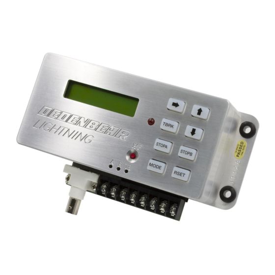
Using #8 screws through the rubber grommets in the base, mount the LIGHTNING away from heat, vibration and
the ignition system.
Make sure the driver can reach the buttons when strapped in and angle the unit, if needed, so the display can be
read straight on.
Wire the LIGHTNING as shown on pages 8-11. Make sure the power lead comes straight from the master switch
and the ground goes to a solid chassis ground, not sheet metal panels.
BUTTON QUICK REFERENCE
INSTALLATION & OPERATION MANUAL
INDEX
Starting Line Control / Super Start ........................................... pg 6
General Info / Definitions .......................................................... pg 7
Transbrake Wiring ..................................................................... pg 8
Throttle Stop & Nitrous Wiring .................................................. pg 9
Linkage Stop & Remote Display ............................................. pg 10
Timed Shifter Wiring ............................................................... pg 11
Setting Parameters ................................................................. pg 12
MODEL NUMBERS
L1 and L2
2650-1303-00 Rev. A
Advertisement

Subscribe to Our Youtube Channel
Related Manuals for Dedenbear LIGHTNING

Summary of Contents for Dedenbear LIGHTNING
- Page 1 Make sure the driver can reach the buttons when strapped in and angle the unit, if needed, so the display can be read straight on. Wire the LIGHTNING as shown on pages 8-11. Make sure the power lead comes straight from the master switch and the ground goes to a solid chassis ground, not sheet metal panels.
-
Page 2: Programming Buttons
The LIGHTNING has many selections that can be programmed for each setting. Each time you push the button for the particular setting you are adjusting, it will step you to the next prompt screen. The LIGHTNING will only ask for the settings needed for the particular mode you are in. - Page 3 To set your transbrake delay you must first choose which delay box type you wish to run by pressing the MODE button. The LIGHTNING will only ask for the settings required for that particular mode. Example: When you are in RUN (DELAY) it will not ask you for THEIR ET setting since you are not crossing over.
- Page 4 THROTTLE STOP TIMERS The LIGHTNING has 2 separate throttle stop controller outputs, the STOP A and the STOP B output. The STOP A output has a shared starting line control (SLC) output while the STOP B is simply a timer. Both outputs work independently from one another allowing control over two separate devices.
- Page 5 • Under the carb “Disc” throttle stops use: LINKAGE / DISC (power turns on at timer 1) • In-line “Linkage” throttle stops use: LINKAGE / DISC (power turns on at timer 1) • Nitrous Oxide systems use: LINKAGE / DISC (power turns on at timer 1) • Dedenbear Solenoid Shifter “Hold type” use: BASE PLATE STYLE (power turns off at timer 1) • CO2 or “Air” shifters use: LINKAGE / DISC (power turns on at timer 1) The last prompt screen that will be displayed is the throttle stop control. To change the type of control, push and hold the RSET button while the screen is showing.
- Page 6 STARTING LINE CONTROL & SUPER START SYSTEM Starting Line Control (SLC) is a shared output with STOP A. This output can be used to control a single throttle stop as a STOP down track to control the E.T., a starting line control to control the staging RPM, or both. If a single throttle stop is used for both starting line and down track duties the staging RPM must be the same as the down track RPM.
- Page 7 “FIRST HIT BY: .023”. This means that you were quicker leaving off your top bulb than your second bulb and that you were .023 seconds quicker. The LIGHTNING released the transbrake off the top bulb hit in this example. If you had cancelled the first two hits by pressing the button a third time, the display would read “LAST CHANCE ACTIVATED”.
- Page 8 4. If you are going to use a rev limiter on the starting line, tie the rev limiter activation wire in with the transbrake wire. 5. Run a 14 gauge wire from the LIGHTNING’s +12 volt terminal to one side of the transbrake button used to launch the car. Run the other side of the button back to the TB Switch terminal on the LIGHTNING.
- Page 9 WIRING FOR BASEPLATE STYLE THROTTLE STOPS WIRING FOR 2 STAGE NITROUS SYSTEM...
- Page 10 Wire the Remote Display unit as shown. Use at least 18 gauge wire connecting the black wire to a solid chassis ground and the red to + 12 volts. Use a 5 amp fuse in the red wire to protect the Remote Display from damage. Connect the display to your LIGHTNING using the transmitting cable included with the display unit.
- Page 11 “2-STAGE” and the type to “LINKAGE / DISC” 2. “Hold” Type Electric Shifter: Hold type shifters such as Dedenbear models SS-2, 3, 4, 5, & 6 require a constant +12v to hold the plunger back. At the shift point +12v is removed and the spring pushes the shifter forward. Set STOP B to “2-STAGE” and the type to “BASEPLATE”...
- Page 12 3.00 3.00 T-STOP B TYPE Baseplate or Linkage/Disc LINK LINK STOP B T-STOP B CONTROL 2-Stage, 4-Stage, Off 2-STG 2-STG 413 West Elm Street • Sycamore, IL • 60178 • (866) 248-6356 www.dedenbear.com • email: sales@autometer.com 2650-1303-00 Rev. A 11/5/13...
Need help?
Do you have a question about the LIGHTNING and is the answer not in the manual?
Questions and answers