Table of Contents
Advertisement
M
u
l
t
i
-
I
n
t
e
r
f
a
c
M
u
l
t
i
-
I
n
t
e
r
f
a
c
(
R
S
-
2
3
(
R
S
-
2
3
M
o
d
e
l
s
3
P
C
M
o
d
e
l
s
3
P
C
(
(
M
o
d
e
l
s
3
P
C
I
O
M
o
d
e
l
s
3
P
C
I
O
Manual Documentation Number 3PCIoUx-1008
e
P
C
I
B
u
s
S
e
r
e
P
C
I
B
u
s
S
e
r
2
/
R
S
-
4
2
2
/
R
S
-
4
8
5
)
2
/
R
S
-
4
2
2
/
R
S
-
4
8
5
)
I
U
2
,
3
P
C
I
U
4
,
3
I
U
2
,
3
P
C
I
U
4
,
3
N
o
n
-
I
s
o
l
a
t
e
d
)
N
o
n
-
I
s
o
l
a
t
e
d
)
a
n
d
a
n
d
U
1
,
3
P
C
I
O
U
2
,
U
1
,
3
P
C
I
O
U
2
,
(
I
s
o
l
a
t
e
d
)
(
I
s
o
l
a
t
e
d
)
i
a
l
C
a
r
d
s
i
a
l
C
a
r
d
s
P
C
I
U
8
P
C
I
U
8
3
P
C
I
O
U
4
3
P
C
I
O
U
4
Advertisement
Table of Contents
Troubleshooting

Related Manuals for B&B Electronics MIport 3PCIOU1

Summary of Contents for B&B Electronics MIport 3PCIOU1
- Page 1 Manual Documentation Number 3PCIoUx-1008...
- Page 2 International Headquarters B&B Electronics Mfg. Co. Inc. 707 Dayton Road Ottawa, IL 61350 USA Phone (815) 433-5100 -- General Fax (815) 433-5105 www.bb-elec.com Website: Sales e-mail: -- Fax (815) 433-5109 orders@bb-elec.com Technical Support e-mail: -- Fax (815) 433-5104 support@bb.elec.com European Headquarters B&B Electronics Westlink Commercial Park Oranmore, Co.
-
Page 3: Table Of Contents
CAUTION: This is an Electrostatic Sensitive Device. Use ESD precautions for safe handling. Before removing the card from the anti-static protective packaging: - Discharge any static electricity buildup on your body by touching a large grounded metal surface or the metal chassis on equipment connected to earth ground by a 3-wire power cord. -
Page 4: Table Of Contents
TABLE OF CONTENTS ...II CHAPTER 1: GENERAL INFORMATION ... 1 ... 1 NTRODUCTION ... 1 EATURES ... 3 PORT ODELS AND EATURES ... 5 UICK TART UIDE ... 7 PECIFICATIONS CHAPTER 2: SERIAL CARD SETUP ... 8 ... 8 ETUP TEPS ESD Precautions ... - Page 5 NT D NSTALLING INDOWS RIVER NT D NSTALLING INDOWS RIVER Windows Settings ... 34 Pre-Installation Steps ... 34 Installing the Driver Software ... 34 Configuring the Serial Ports ... 37 CHAPTER 4: SETTING DRIVER OPTIONS ... 40 ONFIGURING ETTINGS OES NOT APPLY TO FIFO B ...
- Page 6 RS-422/485 S IGNAL ESIGNATIONS AND RS-422/485 Signal Designations ... 60 RS-422/485 D IFFERENTIAL IGNALS RS-422 O ... 61 PERATION RS-422 Limitations ... 61 RS-485 O ... 61 PERATION Send Data Control ... 62 RS-485 T ERMINATION ESISTORS RS-485 N ... 63 ETWORK IASING RS-485 C...
-
Page 7: Chapter 1: General Information
Introduction MIport PCI serial interface cards allow you to add RS-232, RS-422 and RS- 485 interfaces to Windows based computers equipped with a PCI bus. Depending on your choice of card one, two or four optically isolated serial ports, or two, four or eight non-isolated serial ports, can be added. MIport PCI serial cards are Plug and Play compatible, which allows the Windows Operating System and driver to set the addresses and IRQ used by the card. - Page 8 General Information • Conform to the PCI V2.3 Universal PCI specification • RS-232/RS-422/RS-485 interfaces • 2-wire or 4-wire RS-485 operation (half or full-duplex) • Automatic Send Data Control for RS-485 operation • Buffered high speed XR17D15x PCI Bus UARTs (16C550 compatible) with 64 byte FIFOs for input/output with programmable trigger thresholds •...
-
Page 9: Miport Models And Features
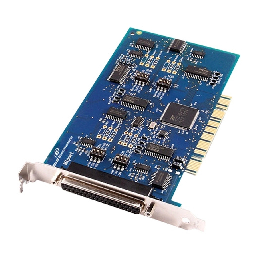
MIport Models and Features Model Ports Interface Number 3PCIOU1 RS-232/422/485 3PCIOU2 RS-232/422/485 3PCIOU4 2 RS-232/422/485 ports 2 RS-422/485 ports Figure 2. MIport Optically Isolated PCI Cards Manual Documentation Number 3PCIoUx-1008 General Information Connectors DB-9 male DB-9 male 2 x DB-9 male... - Page 10 General Information Model Ports Interface Number 3PCIU2 RS-232/422/485 3PCIU4 RS-232/422/485 3PCIU8 4 RS-232/422/485 ports 4 RS-232 ports Figure 3. MIport Non-Isolated PCI Cards Chapter 1 Connectors 2 x DB-9 male DB-37 female (plus DB-37 to 4x DB-9 male cable) DB-78 female (plus DB-78 to 8x DB-9 male cable) Manual Documentation Number 3PCIoUx-1008...
-
Page 11: Quick Start Guide
Quick Start Guide CAUTION: This is an Electrostatic Sensitive Device. Use ESD precautions for safe handling. Before removing the card from the anti-static protective packaging: - Discharge any static electricity buildup on your body by touching a large grounded metal surface or the metal chassis on equipment connected to earth ground by a 3-wire power cord. - Page 12 General Information 11. Select the appropriate COM port, double-click and check properties. 12. Check and set up Port Settings 13. Under Advanced Settings, set Buffer, RTS Control and Hysteresis Level. Change the COM port name, if necessary. 14. If your card was not connected to a peripheral device in Step 5, make your connections now.
-
Page 13: Specifications
Even, odd, none, space or mark Parity 1, 1.5 or 2 Stop Bits Optical Isolation 2000 VDC minimum on all lines (3PCIOU1, Ports are isolated from the PC power and ground, as well as other ports 3PCIOU2, on the same card. 3PCIOU4 only) Connectors... -
Page 14: Chapter 2: Serial Card Setup
Serial Card Setup The following Serial Card Setup section applies to the following PCI cards: • 3PCIOU1 one port optically isolated PCI serial card • 3PCIOU2 two port optically isolated PCI serial card • 3PCIOU4 four port optically isolated PCI serial card •... -
Page 15: Overview Of Operational Modes
Overview of Operational Modes RS-232 Mode In RS-232 Mode MIport serial ports function as buffered standard PC serial ports and operate as DTEs (Data Terminal Equipment). RS-232 interfaces are commonly used for communications with modems, serial printers, and computer-controlled devices such as security equipment, bar code scanners and point-of-sale devices. -
Page 16: Operating Mode Selection
Serial Card Setup In half-duplex operation, the receiver is disabled during transmit (RX and enabled when not transmitting. In full-duplex operation the receiver is always enabled (RX ON). Since RS-485 transmitters are tri-stated when not transmitting, the receive inputs must be biased to ensure the media floats in the Mark state so that the first Space state is detected correctly at the start of the next transmission. -
Page 17: Setting The Dip Switches On Rs-232/422/485 Ports
Setting the DIP Switches on RS-232/422/485 Ports Set the DIP switches to configure the desired operating mode as follows: Switch 1 422/485 Switch 2 TX On TX SD Switch 3 RX SD RX On RS-232 Mode 422/485 TX On RX On RS-422 Mode Figure 5. -
Page 18: Setting The Dip Switches On Rs-422/485 Only Ports
Serial Card Setup DIP Switch 3 (RS-232/422/485 ports) The bottom DIP switch (3) configures the port for half-duplex (two-wire) RS-485 operation or full-duplex (four wire) RS-422/RS-485 operation. Placing the bottom DIP switch in the RX ON position configures the port for four wire operation. - Page 19 Serial Card Setup For RS-485 operation the middle DIP switch is placed in the TX SD position. In this position the transmitter is only enabled when data is being sent. The transmitter is tri-stated when not sending data, allowing other transmitters on the communications line to transmit without interference.
-
Page 20: Installing The Serial Card
Serial Card Setup Installing the Serial Card CAUTION: This is an Electrostatic Sensitive Device. Use ESD precautions for safe handling. Before removing the card from the anti-static protective packaging: - Discharge any static electricity buildup on your body by touching a large grounded metal surface or the metal chassis on equipment connected to earth ground by a 3-wire power cord. -
Page 21: Chapter 3: Driver Software Installation
Installing Windows Vista Driver Software Installation of the MIport driver software on Windows Vista is a three-step process: 1. Windows Vista searches and identifies new hardware that has been installed. 2. You use the Found New Hardware Wizard to install the driver software for the card. -
Page 22: Using The Found New Hardware Wizard
Driver Software Installation Using the Found New Hardware Wizard Windows will detect the PCI card and start the to begin the driver installation. The following dialog box will appear: Wizard Drive software (on CD-ROM) is provided with your MIport card. Do not connect to Windows Update to search for software. -
Page 23: Installing Windows Xp Professional Driver Software
All serial adapter cards should appear in the list. Additional information about the cards can be obtained by double-clicking the name of the card. 3. Click Ports (COM & LPT) All installed ports should appear in the list. The COM port number assigned to each port will be shown. -
Page 24: Using The Found New Hardware Wizard
Driver Software Installation Note: Refer to Chapter 2 of information on DIP switch settings and bias/termination resistors. 6. Install the card in the slot. Use appropriate ESD handling precautions. 7. Power up the computer 8. Insert your driver disc in the CD-ROM drive. Using the Found New Hardware Wizard Windows will detect the PCI card and start the to begin the driver installation. - Page 25 Driver Software Installation Figure 8. The “Install the Card Software Automatically” Dialog 10. To begin the installation of the software for the PCI card, click . Click Install the software automatically Next Windows will find the appropriate files on the CD, then display a dialog box concerning Windows Logo testing for XP.
-
Page 26: Checking The Driver Installation
Driver Software Installation 11. Click Continue Anyway A dialog box will appear indicating the software installation is proceeding. 12. When the Completing the Found New Hardware Wizard appears, click Finish. Port Driver Installation The Welcome to the Found New Hardware Wizard will appear again, indicating it has detected a port on the PCI card. - Page 27 Figure 10. The Device Manager Window 3. In the Device Manager All serial adapter cards should appear in the list. Additional information about the cards can be obtained by double-clicking the name of the card. 4. Click Ports (COM & LPT) All installed ports should appear in the list.
-
Page 28: Installing Windows 2000 Professional Driver Software
Driver Software Installation Installing Windows 2000 Professional Driver Software Installation of the MIport driver software on Windows 2000 Professional is a three-step process: 1. Windows searches for and identifies new hardware that has been installed. 2. You use the Found New Hardware Wizard to install the driver software for the card. -
Page 29: Using The Found New Hardware Wizard
Using the Found New Hardware Wizard Windows will detect the PCI card and start the to begin the driver installation. The following dialog box will appear: Wizard Figure 11. The Windows 2000 Add New Hardware Wizard The driver installation goes through several steps, after finding the driver files. - Page 30 Driver Software Installation Figure 12. The “What do you want Windows to do?” dialog 11. To begin the installation of the software for the PCI card, click Search for a suitable driver for my device, Figure 13. The “Windows will search for new driver” dialog 12.
- Page 31 Driver Software Installation Windows will find the appropriate files on the CD. Figure 14. The “Windows driver file search for the device” dialog 13. To begin the installation of the software for the PCI card, click Next. Windows will display the dialog box.
- Page 32 Driver Software Installation Figure 15. The Digital Signature Not Found Dialog 14. Click A dialog box will appear indicating the software installation is proceeding. 15. When the Completing the Found New Hardware Wizard appears, click Finish. Port Driver Installation The Add New Hardware Wizard will appear again, indicating it has detected a port on the PCI card.
-
Page 33: Checking The Driver Installation
Checking the Driver Installation You may want to check to verify that the new B&B COM ports are now available. 1. From the Windows Desktop → Panel System 2. On the System Properties click the Device Manager will appear: Figure 16. System Properties Screen 3. -
Page 34: Installing Windows 98 Or Me Driver Software
Driver Software Installation Installing Windows 98 or ME Driver Software Installation of the MIport driver software on Windows 98 is a three-step process: 1. Windows searches for and identifies new hardware that has been installed. 2. You use the Found New Hardware Wizard to install the driver software for the card. -
Page 35: Using The Add New Hardware Wizard
Using the Add New Hardware Wizard Windows will detect the PCI card and start the to begin the driver installation. The following dialog box will appear: Figure 17. The Add New Hardware Wizard dialog The driver installation goes through several steps, after finding the driver files. - Page 36 Driver Software Installation Figure 18. The “What do you want Windows to do?” dialog 8. To begin the installation of the software for the PCI card, click then click Search for the best driver for your device, Next Figure 19. The “Windows will search for new drivers” dialog Chapter 3 Manual Documentation Number 3PCIoUx-1008...
- Page 37 Driver Software Installation Select “Specify a location” and choose the E:\ Windows\Drivers\MIport\98_ME folder. NOTE: In Windows ME you will need to select the Driver from this folder: E:\ Windows\Drivers\MIport\98_ME Windows will find the appropriate files on the CD. Figure 20. The “Windows driver file search for the device” dialog 10.
-
Page 38: Checking The Driver Installation
Driver Software Installation 11. Click Finish. Installation will complete automatically. Port Driver Installation The Add New Hardware Wizard will appear again, indicating it has detected a port on the PCI card. Repeat the steps above to install the port driver software. - Page 39 Figure 22. System Properties Screen 3. In the Device Manager All serial adapter cards should appear in the list. Additional information about the cards can be obtained by double-clicking the name of the card. 4. Click Ports (COM & LPT) All installed ports should appear in the list.
-
Page 40: Installing Windows Nt Driver Software
Driver Software Installation Installing Windows NT Driver Software Installation of the MIport driver software on Windows NT is a two-step process: 1. Installing the driver software. 2. Configuring the ports Note: If at some point in the future, you want to update these drivers, remove the old drivers before installing the new version. - Page 41 Driver Software Installation Figure 23. The Install.exe file in Windows NT Explorer 2. Double-click the file. The install.exe MIport Driver v1.0.0 for dialog will appear. Windows NT 4.0 Installation Welcome Figure 24. The NT Driver Installation Welcome Dialog Manual Documentation Number 3PCIoUx-1008 Chapter 3...
- Page 42 Driver Software Installation 3. Click on the Next dialog will appear. 4. Click on the Next Destination Directory 5. Click to install the files in the suggested directory. Next Figure 25. The Select Destination Directory Dialog dialog will appear. Ready to Install! 6.
-
Page 43: Configuring The Serial Ports
Configuring the Serial Ports Before using the serial ports, they must be configured. 1. Open the Control Panel Figure 26. The NT Control Panel Showing the BB Electronics MIport Card Applet Icon 2. Double-click the BB Electronics MIport Card B&B Electronics Multiport Boards port(s) on the MIport card as not assigned. - Page 44 Driver Software Installation Figure 27. Selecting Port Names 4. Click for the port. Settings 5. In the Communications Port Settings bits per second, data bits, parity, stop bits and flow control if they need to be changed from the default values. Figure 28.
- Page 45 8. In the Advanced Settings Transmit buffer: Low, RTS Control Hysteresis level (characters) Note: For more information on advanced settings refer to Chapter 4 Figure 29. The Advanced Port Setting Dialog 9. Click to return to the 10. Click to return to the Cancel 11.
-
Page 46: Chapter 4: Setting Driver Options
Setting Driver Options Configuring Port Settings By entering the Properties dialog a variety of information can be obtained and several port parameters can be configured. 1. On the Ports (COM & LPT) be configured. 2. On the Port Properties The dialog will display the current settings for Bits per second, Data bits, Parity, Stop bits and Flow control. -
Page 47: Setting The Fifo Buffers
Advanced Port Settings you to set the Receive and Transmit FIFO buffer thresholds, RTS Control parameters, Hardware handshaking hysteresis level and the COM port name. Figure 31. The Advanced Settings for COM# dialog Setting the FIFO Buffers MIport cards use UARTs that contain 64-byte transmit and receive FIFO (first in, first out) buffer registers. -
Page 48: Setting The Rts Control Parameter
Setting Driver Options UART will request that the computer transfer the contents of the buffer to program memory. This is intended to optimize the throughput of the data. The default value is 14. Usually this parameter does not have to be changed. Setting the RTS Control Parameter 1. - Page 49 Setting Driver Options Available names for COM numbers are shown. Select a new number from those not “in use”. COM numbers from COM1 to COM256 may be available. COM numbers “in use” may be used by motherboard ports, modems, virtual COM ports for network serial server devices or FAX modems.
-
Page 50: Chapter 5: Installing Linux Driver Software
Installing Linux Driver Software Installing MIport Drivers in Linux Note to the Editor(s): All commands and directories are case sensitive in Linux. When updating this section, be very careful about then things are uppercase or lowercase. Installation of the Linux driver software for MIport cards is a three-step process: 1. -
Page 51: Installing The Driver
2. Remove any temporary files: make clean 3. Make a dependency file: make dep 4. Make the driver file: make Installing the Driver 1. If the user is not root, switch to the root user 2. Install the driver files as root make install Figure 33. - Page 52 Installing Linux Driver Software 3. Make the device nodes: ./bbmknod_sh ./bbmknod_csh 4. Modify the startup script to automatically start the driver: cp /home/username/bbelec/drivers/MIport/rc.bb17d15x /etc/rc.d WARNING: Do not overwrite Note: These scripts will create the device nodes /dev/tty/M0/ and/dev/cum0 for each port, where the 0 is the number of the port. already exists append the commands from: /etc/rc.d/rc.serial /home/username/bbelec/drivers/MIport/rc.serial...
-
Page 53: Checking The Driver Installation
Checking the Driver Installation Open a terminal window and execute the following steps at the command prompt to check the driver installation: 1. If the user is not root, then switch to the root user: 2. Check that the driver is running: /sbin/lsmod | grep bb17d15x 3. -
Page 54: Using The Exar Serial Gui Example Application
Installing Linux Driver Software Using the Exar Serial GUI Example Application The Exar Serial Test GUI is a program included on your MIport software CD that can be used to check the operation of your MIport card. The following procedure describes how to set up and run this application. Preparing the Example Application Files 1. - Page 55 Figure 34. The Blank Application Window 6. Click . The File, Open Figure 35. The Open device dialog box 7. Type the name of the device in the File name box. The name will be ttyM0, ttyM1, etc. Click The screen will change from gray to white and the name of the file will appear at the top of the screen.
-
Page 56: Configuring Port Settings
Installing Linux Driver Software Figure 36. The Open Application Window Configuring Port Settings 1. Click Serial, Port Settings. The Serial port parameters dialog will appear. The dialog will display the current serial port settings. Enter the parameters required for your application. Note: Refer to Chapter 4 for detailed explanations of serial port settings. -
Page 57: Chapter 6: Removing Drivers, Ports And Cards
You may need to remove the card from your system or remove the current driver before installing a driver upgrade. The following sections describe removal procedures. Removing MIport Cards from Win98/ME/2000/2003 Server/XP/Vista Uninstalling the MIport Card 1. In the Device Manager click the card to be uninstalled. -
Page 58: Removing Inf And Pnf Driver Files
Removing Drivers, Ports and Cards Removing INF and PNF Driver Files 1. Open Windows Explorer as follows: From the click → Programs 2. Under the Windows directory expand the inf sub-directory and find the oemX.inf and oemX.PNF files (where X represents the number of the file). - Page 59 Removing Drivers, Ports and Cards Figure 39. Setting the Folder Options to Display Hidden Files 3. Delete the oemx.inf and oemx.pnf files found in Step 2.. CAUTION! Be careful to delete only the files associated with the PCI card you are trying to uninstall. Manual Documentation Number 3PCIoUx-1008 Chapter 6...
-
Page 60: Removing Miport Cards From Windows Nt
Removing Drivers, Ports and Cards Removing MIport Cards from Windows NT Uninstalling the MIport Card 1. The Driver must be uninstalled. Uninstalling the Driver 1. Using Windows NT Explorer B&B installation directory. (The default installation directory is C:\Program Files\B&B Electronics\MIport) Figure 40. -
Page 61: Chapter 7: Rs-232 Connections/Operation
RS-232 Mode In RS-232 Mode MIport serial ports function as buffered standard PC serial ports and operate as DTEs (Data Terminal Equipment). RS-232 interfaces are commonly used for communications with modems, serial printers, and computer-controlled devices such as security equipment, bar code scanners and point-of-sale devices. -
Page 62: Rs-232 Signal Designations
RS-232 Connections/Operation RS-232 Signal Designations The primary RS-232 signals are with GND (ground), they often are referred to as a “3-wire” interface. (Request to Send) and lines used to indicate to the other device that data can be sent or received. These lines may be enabled or disabled on a byte-by-byte basis and are used to prevent buffer overrun or the loss of data. -
Page 63: Rt Control In R-232 Mode
RS-232 Signal Levels RS-232 signal lines are referenced to ground, and each signal can alternate above and below ground. The RS-232 standard specifies output voltages must be no less than +5 volts and no greater than +25 volts to represent a Space on a transmit line (or an asserted handshake line). - Page 64 RS-232 Connections/Operation Figure 42. RTS Control – Select Normal for RS-232 Operation Chapter 7 Manual Documentation Number 3PCIoUx-1008...
-
Page 65: Rs-422/485 Mode
RS-422/485 Mode In RS-422/RS-485 mode MIport serial ports provide two sets of differential signal pairs and signal ground for each port. The RS-422 and RS-485 standards use balanced differential drivers and receivers for each signal. This facilitates greater communication distances than unbalanced systems such as RS-232. -
Page 66: Chapter 8: Rs-422/485 Connections/Operation
RS-422/485 Connections/Operation RS-422/485 Signal Designations Typically RS-422 and RS-485 interfaces use five lines including two signal pairs and ground. One signal pair is the transmit pair, labeled . The other signal pair is the receive pair, labeled TD(B)+ Signal ground is labeled RS-422/485 Differential Signals In RS-422 and RS-485 interfaces signals are sent on differential pairs. -
Page 67: Rs-422 Operation
RS-422 Operation In RS-422 mode, the transmitter is enabled (TX ENABLE) all the time, and the receiver is enabled (RX ENABLE) all the time. Typical point-to-point connections use a transmitter and receiver at each end with two wire pairs connecting them. The transmit lines of the device at one end of the link are connected to the matching receive lines of the device at the other end. -
Page 68: Send Data Control
RS-422/485 Connections/Operation Figure 45. An RS-485 Two-Wire Multidrop Connection Send Data Control MIport cards provide Send Data Control (SDC) for the RS-485 driver and receiver. This is hardware controlled based on the contents of the UART output buffer. When data is present, the driver is enabled; when the output buffer becomes empty, it is disabled. -
Page 69: Rs-485 Termination Resistors
The RS-485 mode is set by configuring the DIP switch setting on the MIport card and by selecting RS-485 Mode under RTS Control in the Advanced COM port settings dialog box. Note: For more information on COM port settings refer to Chapter 2 and Chapter 5 RS-485 Termination Resistors In some applications termination resistors must be connected across the... - Page 70 RS-422/485 Connections/Operation Figure 47. RS-485 Biasing Resistors MIport RS-485 receivers come pre-biased from the factory with a 4.7 kΩ pull-up resistor on the RD(B)+ line and a 4.7 kΩ pull-down resistor on the RD(A)- line. These values are usually adequate for networks that do not implement termination resistors and have 31 or fewer nodes.
-
Page 71: 2-Wire Rs-485 Connections
2-Wire RS-485 Connections The following diagram shows how to wire the DB-9 connector that will plug into your MIport card for 2-wire RS-485 operation. Figure 49. 2-Wire RS-485 Connections 2-Wire RS-485 Mode: Your cables must bridge pins #1 & #3 and pins #2 & #9 in order to receive and transmit. -
Page 72: Rs-422 Point To Multipoints Connection
RS-422/485 Connections/Operation 3. Connect the RD(B) pin #9 on the computer to TD(B) on the device. 4. Connect the RD(A) pin #1 on the computer to TD(A) on the device. 5. Connect the Signal Ground pin #5 to Signal Ground on the device. RS-422 Point to Multipoints Connection In a multi-slave RS-422 connection, TD(B) and TD(A) connect to RD(B) and RD(A) on all the slaves. - Page 73 RS-422/ 485 Connections/Operation Figure 51. 4-Wire RS-422 or RS-485 Connections Manual Documentation Number 3PCIoUx-1008 Chapter 8...
-
Page 74: Chapter 9: Troubleshooting Miport Cards
Troubleshooting MIport Cards Your MIport card should be fully functional when you receive it from the factory. Operational problems encountered on first use will typically be the result of incorrect connections or operation. The following procedure will assist you in locating the source of you problems. Starting Up If you have any trouble starting your system after installing the card, the card may not be properly seated in the slot. -
Page 75: Rs-422/485 Operation
RS-422/485 Operation 1. Check your pinouts. In RS-422 or RS-485 mode the "A" lines should match your "A" or "−" lines. "B" lines should match your "B" or "+" lines. Note: RS-422/485 pinouts are non-standard. 2. Make sure you have RTS Control set to the correct mode: Normal for RS-232, RS-485 Mode for RS-485. - Page 76 Troubleshooting MIport Cards Figure 53. RS-232 Loopback Connector 3. To check 2-wire RS-485 RS-422 or 4-wire RS-485 Loopback Connections, you must either enable the receiver by moving the receive jumper to RX ENABLE mode, or use one port to transmit to another 2-wire RS-485 port or converter by cross connecting and loading ComTest twice, one copy for each port.
-
Page 77: Support
Support USA Office Technicians are available at (815) 433-5100 to answer your questions from 8 AM - 5 PM weekdays (Central Time). Email: support@bb-elec.com European Office Technicians are available at +353 91 792444 to answer your questions from 8:30 AM – 5 PM weekdays (GMT). Email: support@bb-europe.com Manual Documentation Number 3PCIoUx-1008 Troubleshooting MIport Cards... -
Page 79: Setting The Dip Switches On Rs-232/422/485 Ports
Setting the DIP Switches on RS-232/422/485 Ports Set the DIP switches to configure the desired operating mode as follows: Switch 1 422/485 Switch 2 TX On TX SD Switch 3 RX SD RX On RS-232 Mode 422/485 TX On RX On RS-422 Mode Figure 54. -
Page 80: Dip Switch 3 (Rs-232/422/485 Ports)
For RS-485 operation the middle DIP switch is placed in the TX SD position. In this position the transmitter is only enabled when data is being sent. The transmitter is tri-stated when not sending data, allowing other transmitters on the communications line to transmit without interference. DIP Switch 3 (RS-232/422/485 ports) The bottom DIP switch (3) configures the port for half-duplex (two-wire) RS-485 operation or full-duplex (four wire) RS-422/RS-485 operation. - Page 81 DIP Switch 1 (RS-422/485 only) The top DIP switch (1) configures the port for RS-485 or RS-422 operation. For RS-422 operation (which uses two wire pairs and sends point-to-point or point-to-multipoints) the transmitter can be enabled all the time. Placing the middle DIP switch in the TX ON position accomplishes this.
-
Page 83: Appendix B: Connector Pinouts
RS-232 Pinouts Name Description Data Carrier Detect Receive Data Transmit Data Data Terminal Ready Signal Ground Data Set Ready Request to Send Clear to Send Ring Indicator Figure 56. RS-232 Signal Designations and DB-9 Pinout Signal Name Chassis GND Figure 57. RS-232 DB-9 to DB-25 Conversion Cable Pinout Manual Documentation Number 3PCIoUx-1008 Connector Pinouts Direction... -
Page 84: Rs-422/485 Pinouts
Connector Pinouts RS-422/485 Pinouts Name Description RD(A) − Receive Data A TD(B) + Transmit Data B TD(A) − Transmit Data A Signal Ground RD(B) + Receive Data B Figure 58. RS-422/485 Signal Designations and DB-9 Pinout With 2-wire RS-485 mode operation, your connection cable must jumper TD(A) to RD(A) and TD(B) to RD(B). - Page 85 Connector Pinouts Figure 60. 2-Wire RS-485 Wiring Manual Documentation Number 3PCIoUx-1008 Appendix B B -1...
-
Page 87: Appendix C: Troubleshooting With Comtest
is a simple 32-bit Windows (Windows 98, 2000, 2003 Server, ME, XP, NT ComTest 4.0 and Vista) COM port test program included on the MIport CD. (It can also be downloaded from the B&B Electronics website at: allows multiple ports at any address and IRQ, to be opened at any given time. ComTest Features •... -
Page 88: Installing Comtest
Troubleshooting with ComTest Installing ComTest 1. From Windows Explorer, under Windows, Programs, COMTest, find the setup.exe file on the MIport CD. Figure 61. Loading ComTest 2. Run Setup.exe to install ComTest on your program menu under B&B Electronics. Loopback Testing with ComTest To familiarize yourself with the operation of ComTest connect a loopback plug to a COM port on your PC and perform the following procedure: 1. - Page 89 Figure 62. RS-232 Loopback w/Handshaking Connections 2. From the Windows Desktop → Electronics ComTest ComTest will start and then open the 3. Select the COM port you want to access or test. (The drop down box shows available ports that are not currently in use). 4.
- Page 90 Troubleshooting with ComTest 9. When testing is completed, close the program. Note: For more information on using ComTest to troubleshoot MIport cards and software see Chapter 7. Appendix C Manual Documentation Number 3PCIoUx-1008...
-
Page 91: Appendix D: Declaration Of Conformity Statement
DECLARATION OF CONFORMITY Manufacturer’s Name: Manufacturer’s Address: Model Numbers: Description: Type: Application of Council Directive: Standards: Michael J. Fahrion, Director of Engineering Manual Documentation Number 3PCIoUx-1008 Declaration of Conformity B&B Electronics Manufacturing Company P.O. Box 1040 707 Dayton Road Ottawa, IL 61350 USA 3PCIoUx Universal PCI Cards Optically Isolated Serial PCI Card Light industrial equipment... - Page 92 Declaration of Conformity International Headquarters B&B Electronics Mfg. Co. Inc. 707 Dayton Road Ottawa, IL 61350 USA Phone (815) 433-5100 -- General Fax (815) 433-5105 Website: Sales e-mail: orders@bb-elec.com Technical Support e-mail: support@bb.elec.com European Headquarters B&B Electronics Westlink Commercial Park Oranmore, Co.
Need help?
Do you have a question about the MIport 3PCIOU1 and is the answer not in the manual?
Questions and answers