Table of Contents
Advertisement
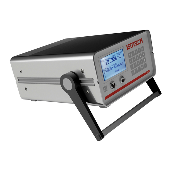
TRUE TEMPERATURE
INDICATOR
MODEL TTI-22
User Maintenance Manual/Handbook
Isothermal Technology Limited, Pine Grove, Southport, PR9 9AG, England
Tel: +44 (0)1704 543830 Fax: +44 (0)1704 544799 Internet: www.isotech.co.uk E-mail: info@isotech.co.uk
The company is always willing to give technical advice and assistance where appropriate. Equally, because of the programme of continual
development and improvement we reserve the right to amend or alter characteristics and design without prior notice. This publication is for
information only.
Page 1 of 49
TTI-22 Iss.04– 11/15
Advertisement
Table of Contents

Related Manuals for Isotech TTI-22

Summary of Contents for Isotech TTI-22
- Page 1 Isothermal Technology Limited, Pine Grove, Southport, PR9 9AG, England Tel: +44 (0)1704 543830 Fax: +44 (0)1704 544799 Internet: www.isotech.co.uk E-mail: info@isotech.co.uk The company is always willing to give technical advice and assistance where appropriate. Equally, because of the programme of continual development and improvement we reserve the right to amend or alter characteristics and design without prior notice.
-
Page 2: Table Of Contents
AFETY NSTRUCTIONS ............................... 6 AFETY YMBOLS ON THE NSTRUMENT ........................... 7 TTI-22 - AN OVERVIEW ................................8 CHECKING THE SUPPLIED PARTS ............................9 OPERATING ELEMENTS AND INSTRUMENT CONNECTIONS ..................10 TTI-22 F RONT ................................10 5.1.1 Display and Function Keys ............................ - Page 3 LATINUM EASURING ESISTORS ...... 40 1990 (ITS-90) ....................... 41 NTERNATIONAL EMPERATURE CALE APPENDIX E: CALIBRATING AND ADJUSTING TTI-22 ......................43 TTI-22 ..........................43 ALIBRATING AND DJUSTING ALIBRATING AND DJUSTING THE ENSOR ........................46 APPENDIX F: CONVERTING THE TEMPERATURE UNIT ......................47 APPENDIX G: FIRMWARE VERSIONS ............................
-
Page 4: Pguarantee
INTERFERENCE WITH OR FAILURE TO PROPERLY MAINTAIN THIS INSTRUMENT MAY INVALIDATE THIS GUARANTEE RECOMMENDATION The life of your ISOTECH Instrument will be prolonged if regular maintenance and cleaning to remove general dust and debris is carried out. We recommend that this instrument to be re-calibrated annually. -
Page 5: About The Instruction Manual
TTI-22. 2.1.2 Installation and Use • TTI-22 is not an explosion-proof instrument and therefore must not be operated in areas with risk of explosion. • TTI-22 is only suitable for inside use. -
Page 6: Maintenance And Service
• Do not use any accessories or wearing parts to TTI-22 other than those supplied or approved by Isothermal Technology Ltd. • Make sure all operators are trained to use the instrument safely and correctly before starting any applicable operations. -
Page 7: Safety Symbols On The Instrument
There is a warning sign on the rear of the instrument, next to the battery compartment. Warning: • Observe the correct polarity when placing the batteries. • Only use 1.5 V AA batteries or 1.2 V AA rechargeable batteries of the same type and charge condition. Page 7 of 49 TTI-22 Iss.04– 11/15... -
Page 8: Tti-22 - An Overview
This provides easy recalibration and good traceability of the temperature measurement. TTI-22 is operated via a menu-driven user interface. The current value, the mean value and the standard deviation of 5 up to 50 values can be continuously displayed. The self-heating effect of the sensor can be determined via the integrated self-heating test. -
Page 9: Checking The Supplied Parts
Checking the Supplied Parts TTI-22 was tested and packed carefully before shipment. However, damages may occur during transport. Keep the packaging material (box, foam piece, transport protection) for possible returns and further questions from the transport and insurance company. Check the delivery for completion by comparing the supplied parts to those noted in Table 4.1 If a part is missing, contact your Isotech representative. -
Page 10: Operating Elements And Instrument Connections
Operating Elements and Instrument Connections TTI-22 Front Side Fig. 5 – 1 Front view 5.1.1 Display and Function Keys Function keys 0,1,2,.., 9 (numerical keys) Menu selection and digit input CE (CLEAR, BACKSPACE) To delete the last entered character ESC (ESCAPE) •... -
Page 11: Instrument Connections On Front Side
Example of a display 5.1.2 Instrument Connections on Front Side You can connect up to two sensors to TTI-22 via 4-pole sockets (Fig. 5 - 1, "CH 1" and "CH 2") type LEMO 1S304. Fig. 5 - 3 Assignment of LEMO socket Page 11 of 49 TTI-22 Iss.04–... -
Page 12: Tti-22 Rear Side
TTI-22 Rear Side Battery compartment for two batteries type AA Ethernet (LAN) RS232 serial interface Inlet for external power adapter Fig. 5 - 4 Rear view 5.2.1 Terminal Assignment of RS232 Pin 1: not assigned Pin 2: TXD (transmit data) -
Page 13: Battery Supply
To open the lid of the battery compartment, stick a screwdriver into the mould and press the lid down, away from the housing. Observe the correct polarity when placing the new batteries (see sign in battery compartment). Charging batteries Remove rechargeable batteries from the instrument for charging them. Page 13 of 49 TTI-22 Iss.04– 11/15... -
Page 14: Putting Tti-22 Into Operation
("Configuration Parameters") Check if the serial number on TTI-22 (on the rear side of the instrument) matches the number on the optional parameter printout ("Configuration Parameters"). If the above-mentioned numbers do not match, be sure to contact the manufacturer or supplier of the instrument. -
Page 15: Putting The Measuring System Into Operation
Putting the Measuring System into Operation Press the <On/Off> key on the lower left front side of the instrument. TTI-22 performs a self-test. If there are no errors, the instrument will enter measuring mode after the self test. 6.2.1 Getting Started with Pre-stored Sensor Parameters If sensor parameters have already been entered and assigned to the sensor inputs 1 and 2 ex factory, TTI- 22 displays the current temperature of the sensors. -
Page 16: Getting Started Without Stored Sensor Parameters
If you switch off TTI-22 with the <On/Off> key, the current operating condition (e.g. mean value mode for 20 values) is stored. If you interrupt the power supply in another way, e.g. by pulling the plug, TTI-22 is deactivated without storing the current operating condition. -
Page 17: Configuring Tti-22
Configuring TTI-22 After being switched on, TTI-22 is in measuring mode. Press the <M> key to change to the menu mode. There are two ways to select a menu item: • Use the arrow keys to move the cursor to the desired item and press the < > key. -
Page 18: Setting Date And Time
Setting the Temperature Unit To select the temperature display unit, switch to menu 2 Edit Configuration > 6 Units & Backlight and set [°C], [K] or [°F]. Fig. 7 - 2 Temperature unit Page 18 of 49 TTI-22 Iss.04– 11/15... -
Page 19: Setting Backlight And Contrast
1 step. Entering Sensor Parameters and Assigning to a Sensor Inlet TTI-22 measures the electrical resistance of the connected platinum sensors and uses it to calculate the temperature via internal formulas (standard case: quadratic equation). These formulas’ coefficients, which are different for each sensor, are called sensor parameters (or calibration parameters). - Page 20 Before entering the calibration parameters, make sure that the date stored in TTI-22 is correct (see Chapter 7.2). The date is stored together with the calibration parameters. Switch to the menu mode and select the menu 2 Edit Configuration. Enter the user password and then select the menu item 3 Sensors > 1 New/Edit Calibr.
- Page 21 = 0.0039126 = -5.9153E – 7 After the example values have been entered, the display shows the following: Fig. 7 - 6 Example for sensor data After the maximum sensor temperature has been exceeded Page 21 of 49 TTI-22 Iss.04– 11/15...
-
Page 22: Assigning Calibration Parameters To A Sensor Channel
SET SENSOR #2: 3 Selecting Display Type To set the display type, go to menu 1 Sel. Display & Start and select one of the 6 display types. Fig. 7 - 7 Selecting the display type Page 22 of 49 TTI-22 Iss.04– 11/15... - Page 23 After this selection TTI-22 automatically goes back into measuring mode. 1 Resistance Display of ohmic resistance with four digits after the decimal point. 2 Temperature Display of temperature with three digits after the decimal point. 3 Resistance Stat. Display of resistance statistics: Display of current resistance, mean value and standard deviation of N previous values.
-
Page 24: Performing A Self-Heating Test
Usually the self-heating of the sensor is considered in the calibration parameters. If the measuring current during calibration strongly deviates from the measuring current in TTI-22, or the thermal resistance (air, water, still or moving) strongly differs, this function is useful for avoiding major errors. The self-heating of sensors that are supposed to measure the temperature of still air, for example, is mostly already too significant to be ignored. -
Page 25: Reading Out Measuring Data
Reading out Measuring Data You can transfer the measuring data to a PC. To do this, connect the PC to the RS232 interface of TTI-22 and use a terminal program or connect the PC to the Ethernet interface of TTI-22 and use a web browser. - Page 26 If you have entered an incorrect command, TTI-22 responds to the PC by sending back the available commands (see Appendix C.2). Table 8.1: PC Commands PC command transfered data, examples GET DATA 18.12.07 17:38:30 R1= +125.02085 Ohm R2= +109.00070 Ohm T1= +64.6448 C...
- Page 27 R0: 100.0000000 A: 0.00390802 B: -5.802000E-07 C: -4.273500E-12 Sensor 5 = N:000419 ITS-90 0-419*C CAL TIME (DAYS): 30 MAX TEMP[*C]: 990 CAL LOW[*C]: 0 CAL HIGH[*C]: 420 R.01: 100.0000000 A: 0.00030000 B: -9.000000E-04 Page 27 of 49 TTI-22 Iss.04– 11/15...
-
Page 28: Transferring Measuring Data Via Ethernet
Be sure to only enter configuration parameters that fit the network you use. If necessary, contact the network administrator. Configure the Ethernet interface at TTI-22 in the menu 2 Edit Configuration > 5 Ethernet Config as follows: Fig. 8 - 3... -
Page 29: Calibrating And Adjusting Tti-22
Calibrating and Adjusting TTI-22 TTI-22 uses an internal reference resistor for measuring the electrical resistance of the sensor. The temperature value is calculated from the resistance measurement via internal formulas. For a precise temperature calculation a regular calibration/adjustment of TTI-22 and the used sensor is necessary. -
Page 30: Locking Calibration Parameters
In locked condition, the date, time, reference resistor parameters and sensor parameters can be accessed, but not altered. To unlock TTI-22, select the menu 4 UNLOCK Device and enter the Lock password. Now TTI-22 is unlocked. In the main menu 4 LOCK Device is displayed. -
Page 31: Overview Of The Menu Structure
1 Sel. Display & Start Display type selection. 2 Edit Configuration Instrument parameter setting. 3 Change User Passw. Entering/changing user password. 4 LOCK Device Locking or unlocking TTI-22 with a "Lock Password". 5 Self.Heat.Test: OFF Switching on/off the self-heating test. Page 31 of 49 TTI-22 Iss.04– 11/15... -
Page 32: Sel. Display & Start (Display Type Selection)
Automatic calibration of the internal reference resistor. 3 Sensors 1 New/Edit Calibr. For entering or editing sensor parameters. Up to 30 calibrations can be stored in TTI-22. Cal.No. Calibration number. Cal. Time Calibration time in days: Period of a calibration’s validity. - Page 33 Fahrenheit (°F) as temperature display unit. 2 Backlight: OFF/ON In this menu you can set the backlight to be automatically activated whenever TTI-22 is switched on. During operation you can use the "Lamp" key to activate or deactivate the backlight at will.
-
Page 34: Appendix A: Technical Data
Number of measuring values: 50) f.s. = full scales This value does not include the calibration uncertainty of the used reference resistor. TTI-22 as High-precision Thermometer (Specifications without Sensor) Pt 100, DIN IEC 751 Temperature measuring range: -200 °C to 850 °C... -
Page 35: General Instrument Data
Input: AC 100 - 240 V, 50 - 60 Hz, 2 W Output: DC 7.5 V, 250 mA Dimensions (L x W x H): 240 x 190 x 110 mm (without handle) Weight approx. 2 kg Page 35 of 49 TTI-22 Iss.04– 11/15... -
Page 36: Appendix B: Declaration Of Conformity
Appendix B: Declaration of Conformity Page 36 of 49 TTI-22 Iss.04– 11/15... -
Page 37: Appendix C: Troubleshooting
Appendix C: Troubleshooting TTI-22 Error Messages If errors occur during TTI-22 operation, an error message is displayed. Error message Cause Correction "ADC ERROR OUT OF The sensor is damaged or the TTI-22 Contact your Isotech representative or RANGE" ADC is defective. -
Page 38: Pc Error Messages
PC Error Messages If TTI-22 is connected to a PC via RS232 interface and data is read out with a terminal program, the PC may receive the following error messages. Error message Cause Correction ??? UNKNOWN The entered command was not Be sure to use the correct syntax. -
Page 39: Problems With Instrument Activation
Problems with Instrument Activation If TTI-22 cannot be switched on or immediately switches itself off again after activation, check the following: If you operate TTI-22 with batteries/rechargeables, check their charge condition. If you operate TTI-22 with a power adapter, check whether the power adapter is correctly plugged If the instrument immediately switches itself off despite functional power supply, check the sensors: •... -
Page 40: Appendix D: Temperature Calculation Methods
Appendix D: Temperature Calculation Methods TTI-22 employs two methods for calculating the temperature from the primarily measured property "ohmic resistance": The DIN IEC 751, which describes the relation between resistance and temperature for industrial sensors, and the ITS-90 (International Temperature Scale 1990), the temperature scale valid for standard thermometers since 1990. -
Page 41: International Temperature Scale 1990 (Its-90)
60 °C too. From the correlation of the temperatures at this point the measuring uncertainty of the thermometer between the calibration points can be determined. A sensor calibrated in this manner together with a TTI-22 can achieve measuring uncertainties of <10mK in the calibrated range. - Page 42 0 – 419.527 TH2O, ESn, EZn a, b 0 – 231.928 TH2O, EIn, ESn a, b 0 – 156.5985 TH2O, EIn 0 – 29.7646 TH2O, SGa -38.8344 – 29.7646 THg, TH2O, SGa a, b Page 42 of 49 TTI-22 Iss.04– 11/15...
-
Page 43: Appendix E: Calibrating And Adjusting Tti-22
Determining suitable calibration intervals If the true value of the reference resistor deviates from the value stored in TTI-22, this will result in a gain error of the resistance measurement in the used measuring model. If the deviation is 3 ppm, for example, the additional deviation of the sensors’... - Page 44 Note the old and the new reference resistor values and the current date. File these records with care. To continue, press the < > key. Press the < > key again in order to store the new value for the internal reference resistor. Page 44 of 49 TTI-22 Iss.04– 11/15...
- Page 45 TTI-22 in Ω Ref[old] value of the externally connected standard resistor in Ω according to calibration certificate mean value of the external standard resistor displayed on TTI-22 (amount of the measuring values used for averaging: N=50) Equipment: TTI-22 Standard resistor [100 Ω...
-
Page 46: Alibrating And Djusting The Ensor
You can calibrate and adjust sensors by connecting a known, certified reference sensor and your un-adjusted sensor to a TTI-22 unit and in this way determining the value of the sensor resistance using a highly precise thermostat at various temperatures. With equations of DIN IEC 751 or ITS-90 you can calculate the sensor parameters. -
Page 47: Appendix F: Converting The Temperature Unit
Conversion of degrees Celsius: T[K] ..Temperature in K t[°C] ..Temperature in °C d[°F] ..Temperature in °F Page 47 of 49 TTI-22 Iss.04– 11/15... -
Page 48: Appendix G: Firmware Versions
New sensors V2.04 09.07.2013 A91IB001EN-C ITS-90: 2 auto-switch ranges available A91IB001EN-D New PC commands Modified menu structure Polynomial of 4th order (new sensor type: approximation by a standard polynomial) Page 48 of 49 TTI-22 Iss.04– 11/15... -
Page 49: Declaration Of Conformity
Declaration of Conformity Page 49 of 49 TTI-22 Iss.04– 11/15...
Need help?
Do you have a question about the TTI-22 and is the answer not in the manual?
Questions and answers