Table of Contents
Advertisement
Advertisement
Table of Contents

Related Manuals for SPI Lasers redPOWER FVCU

Summary of Contents for SPI Lasers redPOWER FVCU
- Page 1 redPOWER FiberView Control Unit FVCU Instructions for Use...
- Page 2 CAUTION: This FVCU must be grounded for safety and to comply with regional electrical codes. Failure to do so may result in incorrect operation of the FVCU. © 2017 SPI Lasers UK Ltd. SM-S00530 Revision A 17 February 2017 Commercial in Confidence...
-
Page 3: Table Of Contents
Process Cycles Other Settings Basic Control Using Serial Communication 10.1 Overview 10.2 Functionality 10.3 Protocol Message References Machine Interface Reference © 2017 SPI Lasers UK Ltd. SM-S00530 Revision A 17 February 2017 Commercial in Confidence redPOWER FVCU Instructions for Use... - Page 4 Figure 8 Fiber Laser Connection Dialog ....................38 Figure 9 FiberView Overview Screen ...................... 39 Figure 10 FiberView Parameter Editor ....................42 © 2017 SPI Lasers UK Ltd. SM-S00530 Revision A 17 February 2017 Commercial in Confidence redPOWER FVCU Instructions for Use...
- Page 5 Down Time Configured in Active Step Parameter Step) ................. 65 Figure 37 Entering Remote Control (Process Cycle Active, Process Cycle Start Input CLEAR, Ramp Down Time Configured in Active Step Parameter Step) ................. 66 © 2017 SPI Lasers UK Ltd. SM-S00530 Revision A 17 February 2017 Commercial in Confidence...
- Page 6 Table 15 Non-Operating Conditions ......................86 Table 16 Electrical Requirements ......................87 Table 17 Dimensions and Weight......................87 Table 18 Contact Information ........................89 © 2017 SPI Lasers UK Ltd. SM-S00530 Revision A 17 February 2017 Commercial in Confidence redPOWER FVCU Instructions for Use...
-
Page 7: Structure And Scope Of These Instructions For Use
FVCU and made available for reference at the location where the FVCU is being used. Additional or replacement copies are available from SPI Lasers. These Instructions for Use are divided into the sections below which provide Users with health and safety information before introducing the FVCU and then guiding them through its installation, operation, maintenance and disposal. -
Page 8: Definition Of Symbols And Terms
Integrator: into equipment, or any person, company or organisation who uses this FVCU in the form as supplied by SPI Lasers. A Laser Integrator is skilled in and understands the integration issues surrounding the use, design and supply of laser products to end users in the end markets which it supplies. -
Page 9: Health And Safety
This FVCU is not intended for controlling lasers other than SPI redPOWER PRISM Fiber Lasers. © 2017 SPI Lasers UK Ltd. SM-S00530 Revision A 17 February 2017 Commercial in Confidence redPOWER FVCU Instructions for Use... -
Page 10: Hazards
SPI Lasers cannot be held liable for any damage resulting from use other than the intended use. The risk lies entirely with the User. Hazards 3.3.1 Laser Hazards This FiberView Control Unit (FVCU) does not in itself present a hazard but may be used to control redPOWER PRISM Fiber Lasers which are potential hazards. -
Page 11: Labelling
However SPI Lasers recognises that Laser Integrators may require the integrated laser system to comply with the directive. SPI Lasers has therefore designed for compliance to parts of the standards listed below which are harmonised to the EMC Directive: ... -
Page 12: Document References
SM-S00499 These documents may be downloaded by going to 'Customer Login' at the top right of SPI Lasers’ home page: www.spilasers.com. © 2017 SPI Lasers UK Ltd. SM-S00530 Revision A 17 February 2017 Commercial in Confidence redPOWER FVCU Instructions for Use... -
Page 13: Redpower Fvcu Tour
5 redPOWER FVCU Tour The redPOWER FVCU builds on many years of experience of SPI Lasers in designing, developing and supplying control systems for fiber lasers into a wide range of industrial laser processing applications. It gives laser integrators the capability to control fiber lasers in industrial laser machines with maximum output power levels from 300W up to many kilowatts. - Page 14 OFF state Indicator is lit if there is an active Warning. Indicator is not lit when there are no alarms or warnings present. © 2017 SPI Lasers UK Ltd. SM-S00530 Revision A 17 February 2017 Commercial in Confidence...
-
Page 15: Software Tools
Software Tools SPI Lasers’ Graphical User Interface, FiberView, allows Users to control this FVCU over a serial interface. Operation of the FVCU using FiberView is described in Section 9. © 2017 SPI Lasers UK Ltd. SM-S00530 Revision A 17 February 2017... -
Page 16: Getting Started
Confirm that the shipping carton contains all items on the shipping inventory list Retain all packaging materials until the FVCU has been commissioned. If anything is missing or defective contact SPI Lasers. See Section 16 for contact details. Unpacking and Handling To avoid the risk of personal injury or damage to the FVCU when lifting or moving, follow good manual handling practice. -
Page 17: Installation
Note: Check PC setting as follows: Control Panel – Regional & Language Options – Advanced Tab – Language for non-Unicode Programs. Set this to English in drop down box. © 2017 SPI Lasers UK Ltd. SM-S00530 Revision A 17 February 2017... -
Page 18: Electrical Connections
To operate a PRISM Fiber Laser using this FVCU a power connection must be made to the PRISM FL Module and to the FVCU, and a control connection must be made from the FVCU © 2017 SPI Lasers UK Ltd. SM-S00530 Revision A 17 February 2017... -
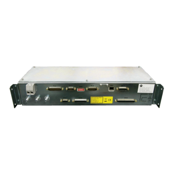
Page 19: Figure 3 Interface Connectors
25-way D-Type male Section connector 7.5.6 Reserved for future expansion Ethernet RJ-45 Section 7.5.5 SK11 Software Shutdown Section 7.5.7 SK12 Reserved © 2017 SPI Lasers UK Ltd. SM-S00530 Revision A 17 February 2017 Commercial in Confidence redPOWER FVCU Instructions for Use... -
Page 20: Figure 4 Star Earthing Configuration
The protective conductor shall support the maximum short-circuit current of the pump diode PSU. © 2017 SPI Lasers UK Ltd. SM-S00530 Revision A 17 February 2017 Commercial in Confidence redPOWER FVCU Instructions for Use... -
Page 21: Table 4 Serial Port Connections
The default configuration should be suitable for the majority of applications, but the © 2017 SPI Lasers UK Ltd. SM-S00530 Revision A 17 February 2017 Commercial in Confidence... -
Page 22: Table 5 Pl5 Machine Interface Pin Out
Table 5 PL5 Machine Interface Pin Out PIN # PIN NAME DEFAULT FUNCTION PEXT PEXT External 24 V DC PEXT PEXT External 24 V DC © 2017 SPI Lasers UK Ltd. SM-S00530 Revision A 17 February 2017 Commercial in Confidence redPOWER FVCU Instructions for Use... - Page 23 7.5.6.3 Connection Configurations The Machine Interface inputs and outputs are provided as sourcing only. Figure 5 below shows the configuration and connection method. © 2017 SPI Lasers UK Ltd. SM-S00530 Revision A 17 February 2017 Commercial in Confidence redPOWER FVCU Instructions for Use...
-
Page 24: Figure 5 Machine Interface Connections Circuits
Figure 5 Machine Interface Connections Circuits © 2017 SPI Lasers UK Ltd. SM-S00530 Revision A 17 February 2017 Commercial in Confidence redPOWER FVCU Instructions for Use... -
Page 25: Figure 6 Pl5 Programmable Inputs
Figure 6 PL5 Programmable Inputs © 2017 SPI Lasers UK Ltd. SM-S00530 Revision A 17 February 2017 Commercial in Confidence redPOWER FVCU Instructions for Use... -
Page 26: Figure 7 Pl5 Programmable Outputs
Remote Control mode are: Laser Start (IN0, Pin 3) This takes the FVCU from the OFF state to the STANDBY (ready) state. © 2017 SPI Lasers UK Ltd. SM-S00530 Revision A 17 February 2017 Commercial in Confidence redPOWER FVCU Instructions for Use... -
Page 27: Table 6 Laser Inputs
False: Sets FVCU to STANDBY or stops a defined process cycle True: Sets FVCU to ON or starts a defined process cycle (if laser already in STANDBY) © 2017 SPI Lasers UK Ltd. SM-S00530 Revision A 17 February 2017 Commercial in Confidence redPOWER FVCU Instructions for Use... - Page 28 5. Table 7 shows the full list of functions that can be configured to apply to any of OUT0 - OUT6 as shown in Table 5. © 2017 SPI Lasers UK Ltd. SM-S00530 Revision A 17 February 2017 Commercial in Confidence...
-
Page 29: Table 7 Laser Status Outputs
Parameter Set / Process Cycle Selected (Bit 2) Parameter Set / Process Cycle Selected (Bit 3) Parameter Set / Process Cycle Selected (Bit 4) © 2017 SPI Lasers UK Ltd. SM-S00530 Revision A 17 February 2017 Commercial in Confidence redPOWER FVCU Instructions for Use... - Page 30 Pins 1 or 2 and 14 or 15 for this function to operate. The active pulse shape must also be set into EPC mode using FiberView. (Refer to Section 9.3.7.) © 2017 SPI Lasers UK Ltd. SM-S00530 Revision A 17 February 2017 Commercial in Confidence...
- Page 31 The actual alarm or warning codes can be read remotely, if required, using the Serial Interface. 7.5.7 SK11 – Software Shutdown For correct operation, the plug supplied fitted into SK11 must not be removed. © 2017 SPI Lasers UK Ltd. SM-S00530 Revision A 17 February 2017 Commercial in Confidence redPOWER FVCU Instructions for Use...
-
Page 32: Table 8 Bdo Integrity Circuit Connections (When Option Specified)
10mA, to ensure reliable operation of the temperature switches. The maximum permissible current is 50mA. Table 8 BDO Integrity Circuit Connections (When Option Specified) Pin № Description FCMS FCMS © 2017 SPI Lasers UK Ltd. SM-S00530 Revision A 17 February 2017 Commercial in Confidence redPOWER FVCU Instructions for Use... -
Page 33: Table 9 Minimum Interface Connection
Must be linked to pin 8 Must be linked to pin 6 7.5.9 SK99 – Service Monitor SK-99 is provided for use by SPI Lasers service personnel only. TB1 – Auxiliary Power Supply 7.5.10 The 24V DC Auxiliary Power Supply connection is a terminal block. The terminals accept wire of 0.5 mm²... - Page 34 All applicable safety requirements for the intended market must be met prior to allowing the FVCU to enter service as part of an integrated laser system. © 2017 SPI Lasers UK Ltd. SM-S00530 Revision A 17 February 2017 Commercial in Confidence...
-
Page 35: Operating Instructions
1. 24V DC Auxiliary PSU. The ‘Run’ status indicators will show green. 2. Allow the 24V DC Auxiliary PSU to stabilise 3. Pump Diode PSUs © 2017 SPI Lasers UK Ltd. SM-S00530 Revision A 17 February 2017 Commercial in Confidence... -
Page 36: Alarms And Warnings
OFF state. Warnings are removed automatically when the condition is removed. Warning conditions include: Back Reflection approaching alarm level Temperature(s) approaching alarm level(s) FVCU in Safe Mode © 2017 SPI Lasers UK Ltd. SM-S00530 Revision A 17 February 2017 Commercial in Confidence redPOWER FVCU Instructions for Use... -
Page 37: The Fvcu And Fiberview For Laser Control
FiberView is an advanced laser control system offering many features not available in other products. However the protocol for controlling Fiber Lasers is available from SPI Lasers to allow users to integrate control of Fiber Lasers into an overall system controller. -
Page 38: Figure 8 Fiber Laser Connection Dialog
It is possible to have more than one instance of FiberView running on a single PC, with each instance controlling a separate Fiber Laser. On connecting to a Fiber Laser, FiberView displays its overview screen, similar to Figure 9. © 2017 SPI Lasers UK Ltd. SM-S00530 Revision A 17 February 2017 Commercial in Confidence... -
Page 39: Figure 9 Fiberview Overview Screen
To operate the Fiber Laser use the buttons in the Tool bar. Click on the green STANDBY Button to enable the Fiber Laser. When the On Button turns black (after a 5s safety delay), click on it to start laser emission. © 2017 SPI Lasers UK Ltd. SM-S00530 Revision A 17 February 2017 Commercial in Confidence... -
Page 40: Parameter Sets
Parameter Set. Absolute mode sets the external analogue control range between 0 and the maximum current demand © 2017 SPI Lasers UK Ltd. SM-S00530 Revision A 17 February 2017 Commercial in Confidence redPOWER FVCU Instructions for Use... - Page 41 Parameter Sets can be edited using the Parameter Editor. Select by Parameter Editor Tab, or View – Windows – Parameter Set Programming on Menu Bar. © 2017 SPI Lasers UK Ltd. SM-S00530 Revision A 17 February 2017 Commercial in Confidence...
-
Page 42: Figure 10 Fiberview Parameter Editor
Sets the pulse width, in µs, for the pulse width duration for the Single Sector Pulse and User Defined Shape output styles. Maximum duration that can be set is 1s. © 2017 SPI Lasers UK Ltd. SM-S00530 Revision A 17 February 2017... - Page 43 Pulse Shape. Any node on the Shape can be selected and dragged to a new position to alter the shape. © 2017 SPI Lasers UK Ltd. SM-S00530 Revision A 17 February 2017...
-
Page 44: Process Cycles
1000 Steps. Figure 12 shows Steps grouped into Process Cycles. The Process Cycles contain from one to 16 Steps. © 2017 SPI Lasers UK Ltd. SM-S00530 Revision A 17 February 2017 Commercial in Confidence redPOWER FVCU Instructions for Use... - Page 45 The Process Cycle Steps contain the attributes listed in Table 11. The attributes can be assigned to each Step in the Process Cycle editor, shown in Figure 13. Figure 13 FiberView Process Cycle Editor © 2017 SPI Lasers UK Ltd. SM-S00530 Revision A 17 February 2017 Commercial in Confidence...
-
Page 46: Other Settings
ON, but its output will be OFF. When the laser enters STANDBY or OFF, the alignment laser output is automatically switched ON. Note: If the alignment laser is left ON, it will automatically switch off after 30 minutes. © 2017 SPI Lasers UK Ltd. SM-S00530 Revision A 17 February 2017 Commercial in Confidence... - Page 47 After clearing the Alarm condition, use the Reset button on the main FiberView Toolbar to reset the indicator status and allow the FVCU to be restarted. © 2017 SPI Lasers UK Ltd. SM-S00530 Revision A 17 February 2017 Commercial in Confidence...
-
Page 48: Basic Control Using Serial Communication
Following the STARTING state duration after a Laser STANDBY command is received. Following the Ramp Down state duration after a Laser STANDBY command is received. © 2017 SPI Lasers UK Ltd. SM-S00530 Revision A 17 February 2017 Commercial in Confidence redPOWER FVCU Instructions for Use... - Page 49 RAMPING UP State When in the RAMPING DOWN or STANDBY states, the RAMPING UP state is entered after receiving a Laser ON command. © 2017 SPI Lasers UK Ltd. SM-S00530 Revision A 17 February 2017 Commercial in Confidence redPOWER FVCU Instructions for Use...
-
Page 50: Protocol Message References
Refer to SM-S00499, Fiber Laser Serial Communications Protocol, for the exact structure and implementation of the above serial protocol commands. © 2017 SPI Lasers UK Ltd. SM-S00530 Revision A 17 February 2017 Commercial in Confidence redPOWER FVCU Instructions for Use... -
Page 51: Machine Interface Reference
Reference Number OUT0 Laser STANDBY 11.3.1 OUT 1 Laser ON / Process Cycle 11.3.2 Active OUT 2 Remote Control 11.3.3 © 2017 SPI Lasers UK Ltd. SM-S00530 Revision A 17 February 2017 Commercial in Confidence redPOWER FVCU Instructions for Use... - Page 52 Remote Control. In this case, the state of the Laser Start input is level sensitive and the state is also dependant on the Laser ON / Process Cycle Start input. © 2017 SPI Lasers UK Ltd. SM-S00530 Revision A 17 February 2017 Commercial in Confidence...
- Page 53 Figure 15 Moving to STANDBY in Remote Control Figure 16 Moving to OFF in Remote Control Note: There is a small switching delay before the Laser Start is acted on (<1ms) © 2017 SPI Lasers UK Ltd. SM-S00530 Revision A 17 February 2017 Commercial in Confidence...
- Page 54 Figure 17 Entering Remote Control (OFF State, Laser Start Set) Figure 18 Entering Remote Control (STANDBY or ON State, Laser Start Clear) © 2017 SPI Lasers UK Ltd. SM-S00530 Revision A 17 February 2017 Commercial in Confidence redPOWER FVCU Instructions for Use...
- Page 55 From the ON state, clearing the input changes the state to the STANDBY state or starts the RAMPING DOWN state if a ramp down time is configured in the active parameter set. © 2017 SPI Lasers UK Ltd. SM-S00530 Revision A 17 February 2017 Commercial in Confidence...
- Page 56 This function is only operational in Remote Control and when the state is the STANDBY state. If this function is configured and SET, when the STANDBY state is © 2017 SPI Lasers UK Ltd. SM-S00530 Revision A 17 February 2017...
- Page 57 STANDBY state. There is a small switching delay before Laser ON is acted on (<1ms) and Laser ON status is SET or CLEARED © 2017 SPI Lasers UK Ltd. SM-S00530 Revision A 17 February 2017 Commercial in Confidence...
- Page 58 Figure 21 Moving to STANDBY in Remote Control (No Ramp Down Time Configured) Figure 22 Moving to STANDBY in Remote Control (Ramp Down Time Configured) © 2017 SPI Lasers UK Ltd. SM-S00530 Revision A 17 February 2017 Commercial in Confidence redPOWER FVCU Instructions for Use...
- Page 59 Before the State has Moved to the STANDBY State Figure 24 Entering Remote Control (STANDBY State, Laser ON Input Set) © 2017 SPI Lasers UK Ltd. SM-S00530 Revision A 17 February 2017 Commercial in Confidence redPOWER FVCU Instructions for Use...
- Page 60 (ON State, Laser ON Input Set) Figure 26 Entering Remote Control (ON State, Laser ON Input Clear, No Ramp Down Time Configured) © 2017 SPI Lasers UK Ltd. SM-S00530 Revision A 17 February 2017 Commercial in Confidence redPOWER FVCU Instructions for Use...
- Page 61 Laser Start is SET. Process Cycle Start can be asserted at any time to start a Process Cycle as long as the state is the STANDBY state. © 2017 SPI Lasers UK Ltd. SM-S00530 Revision A 17 February 2017 Commercial in Confidence...
- Page 62 Process Cycle Active status is CLEARED. Figure 30 Stopping a Process Cycle in Remote Control (Ramp Down Time Configured in Active Step Parameter Step) © 2017 SPI Lasers UK Ltd. SM-S00530 Revision A 17 February 2017 Commercial in Confidence redPOWER FVCU Instructions for Use...
- Page 63 Figure 31 Starting a Process Cycle in Remote Control Before the State has Moved to the STANDBY State Figure 32 Entering Remote Control (STANDBY State, Process Cycle Start Input SET) © 2017 SPI Lasers UK Ltd. SM-S00530 Revision A 17 February 2017 Commercial in Confidence redPOWER FVCU Instructions for Use...
- Page 64 Figure 34 Entering Remote Control (Process Cycle Active, Process Cycle Start Input Set, Ramp Down Time Configured in Active Step Parameter Step) © 2017 SPI Lasers UK Ltd. SM-S00530 Revision A 17 February 2017 Commercial in Confidence redPOWER FVCU Instructions for Use...
- Page 65 (STANDBY State, Process Cycle Start Input Set) Figure 36 Entering Remote Control (Process Cycle Active, Process Cycle Start Input CLEAR, No Ramp Down Time Configured in Active Step Parameter Step) © 2017 SPI Lasers UK Ltd. SM-S00530 Revision A 17 February 2017 Commercial in Confidence...
- Page 66 (either time or shots) has completed and the step is waiting to advance. The Step input is active from the start of the step execution for steps configured with an infinite duration (duration = 0). © 2017 SPI Lasers UK Ltd. SM-S00530 Revision A 17 February 2017 Commercial in Confidence...
- Page 67 The Process Cycle Wait output will clear once the Step input command has been processed. It is not synchronised with the clearing of the Step input. © 2017 SPI Lasers UK Ltd. SM-S00530 Revision A 17 February 2017 Commercial in Confidence...
- Page 68 Triggers when the input transitions from CLEAR to SET only. The function can be used following an alarm condition, once the fault has been identified and cleared, to clear the latched alarm state. © 2017 SPI Lasers UK Ltd. SM-S00530 Revision A 17 February 2017 Commercial in Confidence...
- Page 69 Alarm condition causes the state to move to the OFF state. The alarm condition must be cleared before resetting it otherwise the alarm may reoccur following the reset. © 2017 SPI Lasers UK Ltd. SM-S00530 Revision A 17 February 2017 Commercial in Confidence...
- Page 70 SET, and stopped when the input is CLEAR, or a Trigger (leading edge sensitive), where a single defined pulse configured in the active parameter set © 2017 SPI Lasers UK Ltd. SM-S00530 Revision A 17 February 2017 Commercial in Confidence...
- Page 71 Trigger Source Select - Input Function Sync - Output Function Sequence diagrams Figure 42 Edge Trigger Operation(Pulsed Output Only) © 2017 SPI Lasers UK Ltd. SM-S00530 Revision A 17 February 2017 Commercial in Confidence redPOWER FVCU Instructions for Use...
-
Page 72: Default Output Functionality
PL5 pin number 19 o Output number 0 Basic Function Description o SET when the state is the STANDBY state. © 2017 SPI Lasers UK Ltd. SM-S00530 Revision A 17 February 2017 Commercial in Confidence redPOWER FVCU Instructions for Use... - Page 73 The operation of the function is subtly different depending on whether the FVCU is operating in Parameter Set mode, or Process Cycles mode as follows: © 2017 SPI Lasers UK Ltd. SM-S00530 Revision A 17 February 2017 Commercial in Confidence...
- Page 74 See Figure 20 to Figure 44 for example functionality. 11.3.3 Remote Control (Output Function ID 3) Default connection o PL5 pin number 20 © 2017 SPI Lasers UK Ltd. SM-S00530 Revision A 17 February 2017 Commercial in Confidence redPOWER FVCU Instructions for Use...
- Page 75 This function can be assigned to any of the seven outputs. o Associated function Alarm Reset - Input Function © 2017 SPI Lasers UK Ltd. SM-S00530 Revision A 17 February 2017 Commercial in Confidence redPOWER FVCU Instructions for Use...
- Page 76 Associated functions Laser ON / Process Cycle Start - Input Function Process Cycle Step - Input Function © 2017 SPI Lasers UK Ltd. SM-S00530 Revision A 17 February 2017 Commercial in Confidence redPOWER FVCU Instructions for Use...
-
Page 77: Protocol Message References
This command is used to read the current state of the digital I/O. Refer to SM-S00499, Fiber Laser Serial Communications Protocol, for the exact structure and implementation of the above serial protocol commands. © 2017 SPI Lasers UK Ltd. SM-S00530 Revision A 17 February 2017 Commercial in Confidence... -
Page 78: Alarm And Warning Messages
Driver Power Supply not Present 8m12 Fiber Failure 8m13 BDO Open 8m14 BDO Short 8m15 Humidity 8m16 Internal Communications Failure © 2017 SPI Lasers UK Ltd. SM-S00530 Revision A 17 February 2017 Commercial in Confidence redPOWER FVCU Instructions for Use... - Page 79 Modulator Zone Alarms Code Description 3m02 PRISM FL Module fault 3m03 PRISM FL Module communications failure 3m04 PRISM FL Module communications failure © 2017 SPI Lasers UK Ltd. SM-S00530 Revision A 17 February 2017 Commercial in Confidence redPOWER FVCU Instructions for Use...
-
Page 80: Warning Code Definitions
Where is the zone associated with the warning. is the module number to identify devices where there is more than one. © 2017 SPI Lasers UK Ltd. SM-S00530 Revision A 17 February 2017 Commercial in Confidence redPOWER FVCU Instructions for Use... - Page 81 1130 High laser tray temperature 1131 High internal optics temperature 1133 High diode tray temperature 1148 Modulator fault detected © 2017 SPI Lasers UK Ltd. SM-S00530 Revision A 17 February 2017 Commercial in Confidence redPOWER FVCU Instructions for Use...
- Page 82 Back reflection protection disabled 4m05 Excessive back reflections detected 12.2.5 Machine Interface Zone Alarms Code Description 5101 Using default Machine Interface configuration © 2017 SPI Lasers UK Ltd. SM-S00530 Revision A 17 February 2017 Commercial in Confidence redPOWER FVCU Instructions for Use...
- Page 83 12.2.6 PSU Zone Warnings Code Description 7150 PSU not present. 7151 PSU charge fault © 2017 SPI Lasers UK Ltd. SM-S00530 Revision A 17 February 2017 Commercial in Confidence redPOWER FVCU Instructions for Use...
-
Page 84: Maintenance
Occasionally, the outside of the FVCU may require cleaning to assure full and clear visibility of the warning labels. Before cleaning disconnect the FVCU from the power supplies. Clean only with a clean damp cloth and if any labels become displaced contact SPI Lasers immediately for replacements. -
Page 85: Disposal
WEEE Directive on waste electrical and electronic equipment (WEEE) for a product of its class. © 2017 SPI Lasers UK Ltd. SM-S00530 Revision A 17 February 2017 Commercial in Confidence... -
Page 86: Specifications
Table 15 Non-Operating Conditions Parameter Value Units Temperature (Storage) 0 to +70 °C 0 – 95 (non-condensing) Humidity (Storage) % RH © 2017 SPI Lasers UK Ltd. SM-S00530 Revision A 17 February 2017 Commercial in Confidence redPOWER FVCU Instructions for Use... -
Page 87: Utility Requirements
The power supply should be appropriately approved and protected 15.4 Mechanical Specifications Table 17 Dimensions and Weight Parameter Value Unit Height Width Depth Weight © 2017 SPI Lasers UK Ltd. SM-S00530 Revision A 17 February 2017 Commercial in Confidence redPOWER FVCU Instructions for Use... -
Page 88: General Information
The SPI Lasers logo, SPI, GTWave, redPOWER and redENERGY are trademarks (registered or applied for) of SPI Lasers in at least one of the United States of America, the United Kingdom, the European Community and China, and in various other territories throughout the world. -
Page 89: Contact Information
Product Support productsupport@spilasers.com Tel: +44 (0)1489 779696 - Option 2 Or contact your local distributor. productsupportasia@spilasers.com Contact your local office number © 2017 SPI Lasers UK Ltd. SM-S00530 Revision A 17 February 2017 Commercial in Confidence redPOWER FVCU Instructions for Use... -
Page 90: Customer Service
FVCU from the integrated laser system and make it safe and, if the FVCU is to be returned to SPI Lasers, to ensure that all relevant return documentation is in place before shipment. Details of documentation requirements and copies can be obtained where required from SPI Lasers.
Need help?
Do you have a question about the redPOWER FVCU and is the answer not in the manual?
Questions and answers