Table of Contents
Advertisement
Quick Links
Download this manual
See also:
Instruction Manual
Errata Sheet
January 2006
Caged 249 Series Displacer Sensors
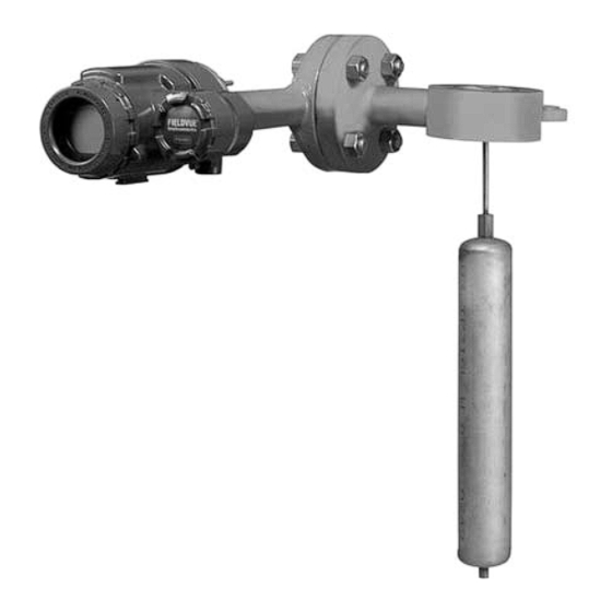
Type 249W Cageless Wafer Style Level Sensor
This errata sheet provides updated information
(refer to table 1) on displacer and torque tube
materials and information regarding simulation of
process conditions for calibration of Level-Trol
controllers and transmitters.
Table 1. Displacer and Torque Tube Materials
Part
Standard Material
Displacer
304 Stainless Steel
Displacer Stem,
Driver Bearing,
316 Stainless Steel
Displacer Rod and
Driver
Torque Tube
N05500
1. N05500 is not recommended for spring applications above
232_C (450_F). Contact your Emerson Process Managementt
sales office or application engineer if temperatures exceeding this
limit are required.
The following Instruction Manuals
Instruction Manual Title
Other Materials
316 Stainless Steel,
N10276, N04400,
Plastic, and Special
Alloys
N10276, N04400,
other Austenitic
Stainless Steels, and
Special Alloys
316 Stainless Steel,
(1)
N06600, N10276
Errata Sheet
for
Simulation of Process Conditions for Calibration
of Level-Trol
R
Contact your Emerson Process Management sales
office for information on obtaining the Supplement to
249 Series Sensors Instruction Manual: Simulation of
Process Conditions for Calibration of Level-Trols -
Form 5767 (part number D103066X012).
Neither Emerson
Management, Fisher
affiliated entities assumes
responsibility for the selection, use,
and maintenance of any product.
Responsibility for the selection, use,
and maintenance of any product
remains with the purchaser and
end-user.
2500-249 Series
Form Number
1802
5729
R
Controllers and Transmitters
Note
R
, Emerson Process
R
, nor any of their
Date
May 2003
March 2005
Advertisement
Table of Contents

Related Manuals for Fisher 249W


Summary of Contents for Fisher 249W
- Page 1 Form Number Date Caged 249 Series Displacer Sensors 1802 May 2003 Type 249W Cageless Wafer Style Level Sensor 5729 March 2005 This errata sheet provides updated information Simulation of Process Conditions for Calibration (refer to table 1) on displacer and torque tube...
- Page 2 January 2006 Level-Trol and Fisher are marks owned by Fisher Controls International LLC, a member of the Emerson Process Management business division of Emerson Electric Co. Emerson, Emerson Process Management, and the Emerson logo are trademarks and service marks of Emerson Electric Co.
-
Page 3: Table Of Contents
Level-Trol Controllers and Transitters Figure 1. Type 249W Sensor with DLC3000 Series Parts Ordering ...... -
Page 4: Type Number Description
Type Number Description of the displacer rod for a given displacement change, it will twist a specific amount for each D Type 249W—3- or 4-inch, ANSI Class 150, increment of buoyancy change. This rotation is 300, 600 steel cageless sensor. -
Page 5: Educational Services
STILLWELL REQUIRED AROUND DISPLACER IF THE FLUID IS IN A STATE OF CONTINUOUS AGITATION W8266 / IL Figure 4. Type 249W Sensor Top Mounted on Vessel Educational Services For information on available courses for Type 249W level sensors, as well as a variety of other products,... -
Page 6: Installation On Top Of Vessel
CAGE WITH SIDE CONNECTIONS CAGE WITH TOP AND BOTTOM CONNECTIONS Figure 5. Type 249W Sensor Cage-Mounted on Side of Vessel side of the vessel as shown in figure 5. The sensor To attach the sensor body to the vessel requires a... -
Page 7: Vessel Or Displacer Cage
Instruction Manual Form 5729 249W Level Sensor May 2006 dimensions for Type 249W sensor and DLC3000 plumb so that the displacer does not strike the side Series controller, and figure 8 provides overall of the cage. envelope dimensions for Type 249W and 2500 Series controller or transmitter. - Page 8 Instruction Manual Form 5729 249W Level Sensor May 2006 STYLE 2 CAGE WITH TOP AND LOWER SIDE VESSEL CONNECTIONS STYLE 1 GE06686 CAGE WITH TOP AND BOTTOM VESSEL CONNECTIONS GE06685 3- OR 4-INCH CLASS 150, 300, OR 600 FLANGE 356 mm...
- Page 9 2.38 4-INCH 3.00 (24.00) HEAT INSULATOR NOTES: EXTENSION 1 DIMENSION G IS CUSTOMER SPECIFIED 2. DISPLACER LENGTH ILLUSTRATED IS 14-INCHES 10C0786-B / IL (INCH) Figure 7. Overall Envelope Dimensions for Type 249W / DLC3000 for Mounting on Customer Supplied Cage...
- Page 10 3.00 (9.41) (2.87) (2.87) (9.12) (14.00) (14.00) NOTES: 1 DIMENSION G IS CUSTOMER SPECIFIED 2. DISPLACER LENGTH ILLUSTRATED IS 14-INCHES (INCH) GE06028-A / IL Figure 8. Overall Envelope dimensions for Type 249W / 2500 for Mounting on Customer Supplied Cage...
-
Page 11: Mounting The Sensor On The Process
Figure 10. Displacer and Displacer Rod Connections displacer through the wafer body after it is positioned on the connecting flange. In this case, install the Figure 9. Positioning Type 249W Wafer Body on the Connecting Flange displacer in step 4. -
Page 12: Maintenance
Type Thread the nut back onto the stud. 249W sensor is installed. 8. Tighten all nuts in a crisscross fashion to the D Drain the process liquid from the torque recommended in tables 2 or 3. - Page 13 D liquid that becomes pressurized due to a change in temperature. The procedures below apply to the Type 249W D liquid that is flammable, assembly as shown in figure 14. Refer to figure 14 hazardous, or corrosive.
-
Page 14: Removing The Displacer And Stem
Instruction Manual Form 5729 249W Level Sensor May 2006 Removing the Displacer and Stem displacer and displacer rod before removing the wafer body, remove the cotter spring (key 10). WARNING Be careful not to let the displacer slip and drop into the bottom of the... -
Page 15: Replacing The Displacer Rod/Driver Assembly
Instruction Manual Form 5729 249W Level Sensor May 2006 5. Replace worn or damaged parts as necessary. 5. If necessary, replace the displacer rod/driver Return the displacer or stem end piece to the assembly and install it on the knife edge of the displacer rod/driver assembly. -
Page 16: Replacing The Torque Tube Arm And Changing The Mounting
Instruction Manual Form 5729 249W Level Sensor May 2006 DISPLACER ROD ASSEMBLY ROTARY SHAFT TORQUE TUBE OUTER TUBE END POSITIONING PLATE DRIER BEARING W0145-1*/IL W0654-1/IL REMOVAL OR INSTALLATION OF POSITIONING PLATE EXPLODED VIEW OF TORQUE TUBE AND DISPLACER ROD ASSEMBLY Figure 13. -
Page 17: Simulation Of Process Conditions For Calibration
Instruction Manual Form 5729 249W Level Sensor May 2006 4. Remove the driver bearing bolts (key 8), 5. Install the driver bearing (key 7), displacer displacer rod/driver assembly (key 5), and driver rod/driver assembly (key 5), and bearing bolts (key bearing (key 7). -
Page 18: Parts Ordering
Components that are not Note supplied by Emerson Process Management should not, under any Neither Emerson, Emerson Process circumstance be used in any Fisher Management, Fisher, nor any of their instrument. Use of components not affiliated entities assumes supplied by Emerson Process... -
Page 19: Parts List
Instruction Manual Form 5729 249W Level Sensor May 2006 PARTS NOT SHOWN 23 19B3127 Figure 14. Type 249W Sensor Construction Parts List Description Part Number Torque Tube Assy Std wall Description Part Number N05500 (std w/WCC steel) 1K4493X0012 Wafer Body... - Page 20 Instruction Manual Form 5729 249W Level Sensor May 2006 Description Part Number Description Part Number Displacer Displacer(1) (cont’d) 2-3/8 x 14 inches (62 cubic inches) 1-1/8 x 96 inches (95 cubic inches) 3.75 pounds (1400 psi) 4.75 pounds S30400 15A4547X042...
- Page 21 Instruction Manual Form 5729 249W Level Sensor May 2006 Description Part Number Description Part Number Hex Nut Bolt Stud (4 req’d) 3-inch Wafer Body (8 req’d) 3-inch Wafer Body 4-inch Wafer Body (4 req’d) For SA-193 B7 bolting 1A3544X0312 For SA-193 B7 bolting...
- Page 22 May 2006 Fisher and Level-Trol are marks owned by Fisher Controls International LLC, a member of the Emerson Process Management business division of Emerson Electric Co. Emerson Process Management, Emerson, and the Emerson logo are trademarks and service marks of Emerson Electric Co.
Need help?
Do you have a question about the 249W and is the answer not in the manual?
Questions and answers